Getting Started with Multicore Modeling and Targeting for Infineon AURIX TC4x Microcontrollers
This example shows how to use SoC Blockset™ Support Package for Infineon® AURIX™ Microcontrollers for multicore modeling and communication between two cores on an Infineon AURIX microcontroller. This example uses a top-level model and two referenced models for two-way multicore data communication. The model supports both simulation and code generation. You can simulate the model and deploy the code on an Infineon AURIX TC4xx TriBoard using the Soc Builder tool and observe the blinking of the configured LEDs of each core to verify the communication between the cores.
Supported Hardware
Infineon AURIX™ TC4x - TriBoards
Available Models
The example includes the top-level model with two referenced models using TriCore 0 and TriCore 1 processing units. Open the top-level tc4x_IpcTopModel model.
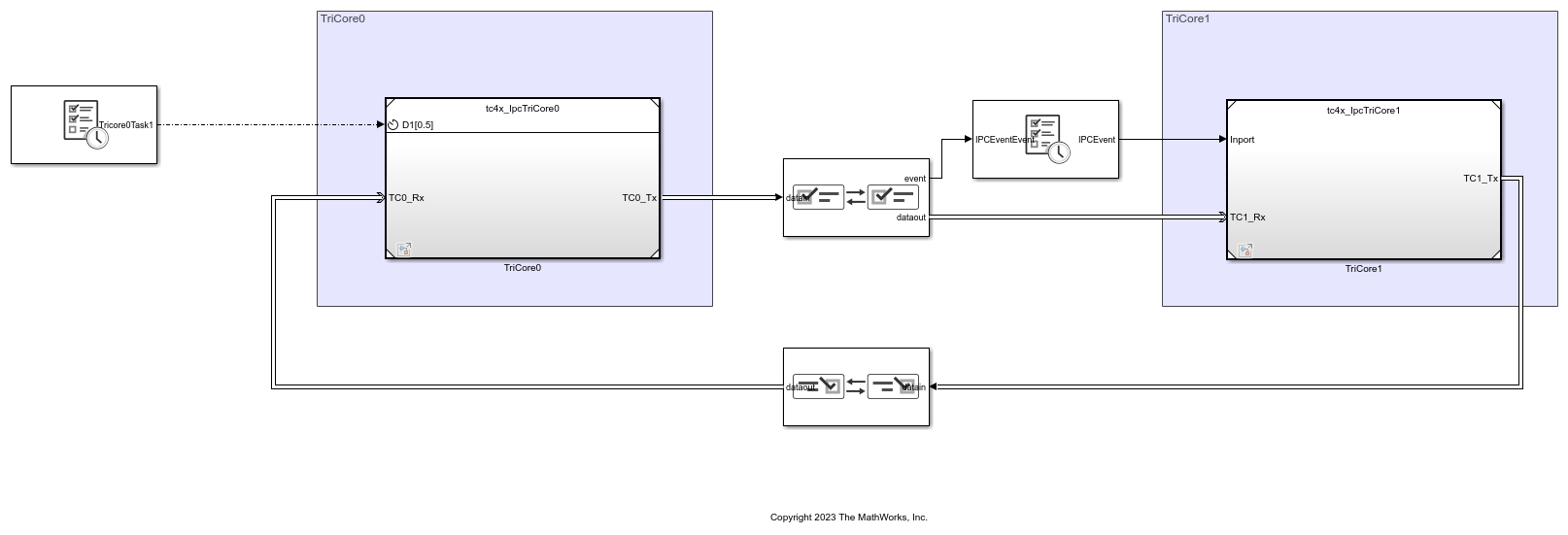
The preconfigured TriCore0 model sends data to the Interprocess Data Channel block at every 0.5 seconds by using the Interprocess Data Write block. The preconfigured TriCore1 model receives the data by using the Interprocess Data Read block.
You can define the interprocess communication (IPC) event for TriCore1 in the Hardware Mapping tool by navigating to Hardware > Hardware Mapping in the Simulink toolstrip.

The TriCore1 model sends the received data through Interprocess Data Channel block and TriCore0 model asynchronously receives the data.
Open the TriCore0 referenced tc4x_IpcTriCore0 model.

This referenced model comprises of pulse and a repeating staircase signals for simulation. Analyze the uint16 type 1 X 2 vector output (pulse signal and repeating staircase signal) of the Mux block.
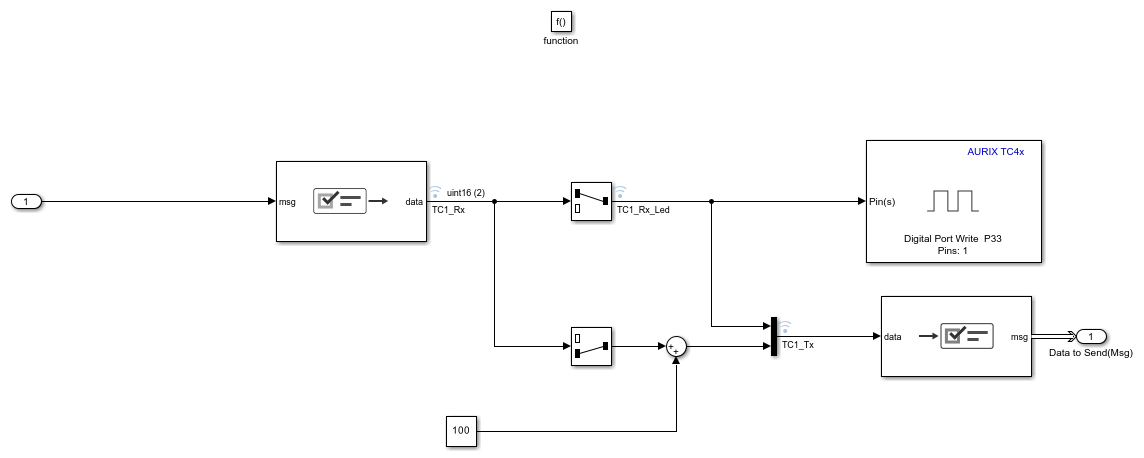
Open the TriCore1 referenced tc4x_IpcTriCore1 model.
Configure Top-Level Model
This example model uses three LEDs on the Infineon AURIX TC4xx board for the verification of bi-directional data communication between the participating cores:
TriCore0 uses Port 13, Pin 0 for Digital Port Write block and Port 33, Pin 0 for Digital Port Write1 block
TriCore1 uses Port 33, Pin 1 for Digital Port Write block
You can define these pins using the Hardware Mapping tool by navigating to Hardware > Hardware Mapping in the Simulink toolstrip.

This configuration of peripherals ensures that the following data flow is implemented using LEDs upon deployment of the model on the board:
LED Port 33-Pin 0 and Port 33-Pin 1 blink simultaneously and in sync when data TriCore0 sends data to TriCore1 using the Interprocess Data Channel block available at the top part of the model. This data flow implies that TriCore1 receives and processes data asynchronously even though the two cores are running at different rates.
LED Port 13-Pin 0 blinks with an offset of 1 sample when TriCore1 sends data to TriCore0 using the Interprocess Data Channel1 block available at the bottom part of the model. This data flow implies that bi-directional communication between cores of the Infineon AURIX TC4xx TriBoard can be achieved by applying offsets.

Configure TriCore0 and TriCore1 Referenced Models
1. Open the tc4x_IpcTriCore0 model.
2. Press Ctrl+E or click Modeling > Model Settings to open Configuration Parameters dialog box.
3. Select the Hardware Implementation pane and ensure that the following parameters are set to define the communication between TriCore0 and TriCore1.

4. Open the tc4x_IpcTriCore1 model.
5. Press Ctrl+E or click Modeling > Model Settings to open Configuration Parameters dialog box.
6. Select the Hardware Implementation pane and ensure that the Processing Unit is set correctly. There is no need to define TriCore0 as the core to which TriCore1 communicates because TriCore0 can communicate with all the cores.

Simulate Model
1. Open the top-level tc4x_IpcTopModel model.
2. Click Run on the Simulation tab to simulate the model.
3. Click Data Inspector on the Simulation tab to view and analyze different transmitting and receiving signals at the referenced models. The model implements two-way multicore data communication by transmitting pulse and staircase signals from Tricore0 to Tricore1 and vice-versa.
Observe the transmitted pulse signal
TC0_Tx_Ledin TriCore0 and received pulse signalTC1_Rx_Ledin TriCore1. These signals are in sync, as TriCore1 is triggered via IPC Interrupt. The pulse signal in TriCore0 blinks the LED at every 0.5s.

Observe the transmitted staircase signal
TC0_Tx_Ledin TriCore0 and received pulse signalTC1_Rx_Ledin TriCore1. These signals are in sync, as TriCore1 is triggered via IPC Interrupt. The pulse signal in TriCore0 blinks the LED at every 0.5s.

Observe the transmitted pulse signal
TC1_Rx_Ledin TriCore1 and received pulse signalTC0_Rx_Ledin TriCore0. There is an offset between these signals as TriCore0 runs at a discrete rate and receives the data sent by TriCore1 in the next sample.

Observe the transmitted staircase signal
TC1_Tx_(2)in TriCore1 and received pulse signalTC0_Rx(2)in TriCore0. There is an offset between these signals as TriCore0 runs at a discrete rate and receives the data sent by TriCore1 in the next sample.

Generate Code and Run Model to Target Hardware
Complete the following steps to generate code and run the model on the target hardware.
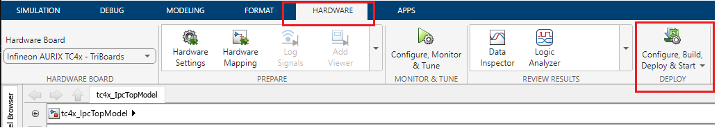
1. Click Configure, Build, Deploy & Start on the Hardware tab to launch the SoC Builder tool.
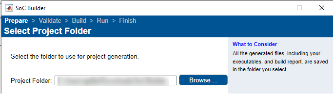
2. In the SoC Builder, prepare the model by first specifying the folder to use for project generation. Click Next.
3. In the Review Hardware Mapping section, click View/Edit to confirm the Hardware Mapping and click Next.
4. In the Validate Model section, click Validate to check the model against the selected board (Infineon AURIX TC4x - TriBoards).

If the message - Model validation successfully finished - appears, click Next.
5. In the next section Build Model, click Build. This process generates the binary executable files in the specified folder from step 2. Click Next after the build is successful.
6. Connect the hardware (Infineon AURIX Tc4x board) to the host computer.
7. In the SoC Builder screen, and click Load and Run. This action loads the generated binary from step 5 to the connected board, programs the processor, and runs the application. Click Finish to close the SoC Builder.
8. Download and install the One Eye tool from Infineon to monitor signals from the hardware. Before using the One Eye tool, ensure that you download and install the latest version of the DAS tool.
9. Open the One Eye tool. Load the One Eye configuration file tc4x_IpcTopModel.OneEye shipped with this example by clicking File > Load Configuration in the One Eye tool. Load the tc4x_IpcTopModel_sw_TriCore0.elf file generated in step 7 by clicking Load ELF file in Debug box viewer. Reset the hardware and check the DAS connection status to monitor the signals.

10. Load the tc4x_IpcTopModel_sw_TriCore1.elf file generated in step 7 by clicking Load ELF file in Debug box viewer. Reset the hardware and check the DAS connection status to monitor the signals.

More About
You can also select a web site from the following list:
Americas
- América Latina (Español)
- Canada (English)
- United States (English)
Europe
- Belgium (English)
- Denmark (English)
- Deutschland (Deutsch)
- España (Español)
- Finland (English)
- France (Français)
- Ireland (English)
- Italia (Italiano)
- Luxembourg (English)
- Netherlands (English)
- Norway (English)
- Österreich (Deutsch)
- Portugal (English)
- Sweden (English)
- Switzerland
- United Kingdom (English)