Main Content

Excitation System

Provide excitation system for synchronous machine and regulate its terminal voltage in generating mode

  • Excitation System block

Libraries:
Simscape / Electrical / Specialized Power Systems / Electrical Machines / Synchronous Machine Control

Description

The Excitation System block is a Simulink® system implementing a DC exciter described in [1], without the exciter's saturation function. The basic elements that form the Excitation System block are the voltage regulator and the exciter.

The exciter is represented by the following transfer function between the exciter voltage Vfd and the regulator's output ef:
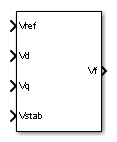
Vfdef=1Ke+sTe.

Examples

The power_turbine example illustrates the use of the Synchronous Machine associated with the Hydraulic Turbine and Governor (HTG) and Excitation System blocks.

Ports

Input

expand all

Desired value, in pu, of the stator terminal voltage.

vd component, in pu, of the terminal voltage.

vq component, in pu, of the terminal voltage.

Connect this input to a power system stabilizer to provide additional stabilization of power system oscillations.

Output

expand all

Field voltage, in pu, for the Synchronous Machine block.

Parameters

expand all

To edit block parameters interactively, use the Property Inspector. From the Simulink Toolstrip, on the Simulation tab, in the Prepare gallery, select Property Inspector.

Time constant Tr, in seconds (s), of the first-order system that represents the stator terminal voltage transducer.

Gain Ka and time constant Ta, in seconds (s), of the first-order system representing the main regulator.

Gain Ke and time constant Te, in seconds (s), of the first-order system representing the exciter.

Time constants Tb, in seconds (s), and Tc, in seconds (s), of the first-order system representing a lead-lag compensator.

Gain Kf and time constant Tf, in seconds (s), of the first-order system representing a derivative feedback.

Limits Efmin and Efmax are imposed on the output of the voltage regulator. The upper limit can be constant and equal to Efmax, or variable and equal to the rectified stator terminal voltage Vtf times a proportional gain Kp. If Kp is set to 0, the former applies. If Kp is set to a positive value, the latter applies.

Initial values of terminal voltage Vt0 (pu) and field voltage Vf0 (pu). When set correctly, they allow you to start the simulation in steady state. Initial terminal voltage should normally be set to 1 pu. Both Vt0 and Vf0 values are automatically updated by the load flow utility of the Powergui block.

References

[1] “Recommended Practice for Excitation System Models for Power System Stability Studies,” IEEE® Standard 421.5-1992, August, 1992.

Extended Capabilities

C/C++ Code Generation
Generate C and C++ code using Simulink® Coder™.

Version History

Introduced before R2006a