Main Content

SPST Relay

Single-pole single-throw relay with delays and faults

Since R2019b

  • SPST Relay block

Libraries:
Simscape / Electrical / Switches & Breakers / Relays

Description

The SPST Relay block models a single-pole single-throw relay. The block has three potential states:

  • De-energized — The common contact, C, changes from being connected to disconnected from the normally open contact, S.

  • Energized — The common contact, C, changes from being disconnected to connected to the normally open contact, S.

  • Open Circuit — The relay is open. The common contact, C, is not connected to the normally open contact, S.

You can:

  • Control the relay state using a physical signal input port or electrical conserving ports.

  • Output the relay state.

  • Delay the breaking and making of the connection.

  • Introduce a behavioral or temporal fault that results in a stuck connection, an open circuit, or degraded contact resistance.

Relay State Control

The block has two control variants:

  • Physical signal (PS) control — The state of the relay depends on how the value of the input physical signal compares to the relay threshold. The relay threshold, th, is the value that you by specify for the Threshold parameter.

  • Electrical control — The state of the relay depends on how the current through the positive and negative electrical conserving ports, which represent the relay winding, compares to the relay upper and lower thresholds. The upper and lower thresholds depend on the values that you specify for the parameters in the Winding settings.

For the PS control variant, at the start of simulation:

  • If the input signal, PS, is less than or equal to th, the relay is de-energized and the common contact, C, disconnects from the normally open contact, S.

  • If the input signal, PS, greater than th, the relay is energized and C connects to the normally open contact, S.

After the simulation starts, if PS rises above th, the block goes from a de-energized state to an energized state and the CS connection closes after the delay specified in Time-to-make C-S connection.

If the block goes from an energized state to a de-energized state, that is PS falls to or below th, the CS connection breaks after the delay specified in Time-to-break C-S connection.

For the electrical control variant, the upper and lower thresholds depend on the specified values for the Rated voltage, Percent rated voltage to energize, Percent rated voltage to de-energize, and Winding series resistance parameters. The rated current is:

irated=Vratedrcoil.

The equation for the upper current threshold, ienergized, is:

ienergized_current=RatedVoltage*PercentratedvoltagetoenergizeWindingseriesresistance.

The equation for the lower current threshold, ide-energized, is:

ideenergized_current=RatedVoltage*PercentratedvoltagetodeenergizeWindingseriesresistance.

At the start of simulation, if the control current is greater than ienergized, the relay is energized and C connects to the normally open contact, S.

After the start of simulation, if the current rises above ienergized, the block goes from a de-energized state to an energized state. The CS connection closes after the delay specified in Time-to-make C-S connection.

If the current falls below ide-energized, the block goes from an energized state to a de-energized state. The CS connection breaks after the delay specified in Time-to-break C-S connection.

Output the Relay State

To view the relay state, expose port x, a physical signal port that outputs the state of each connection. To expose the x port, in the Main settings, set State port to Visible.

The table shows how the state of the relay relates to the state of the connection. A closed connection has a state of 1. An open connection has a state of 0.

Relay and Connection States

CS Connection StateRelay State
0De-energized or open circuit
1Energized

Connection Delays

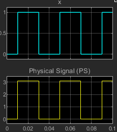
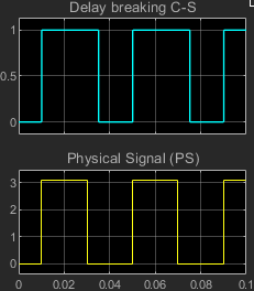
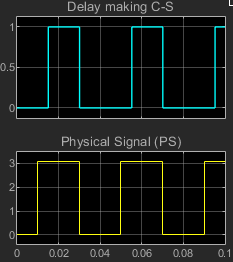
You can specify delays for making and breaking connections in the Mechanical settings. The table shows how the make and break time delays affect the connections between contacts S1 and S2 and the common contact, C.

Mechanical SettingsRelay StateCS Connection StateResults, with CS in Blue and PS in Yellow
ParameterValue
Time-to-break C-S connection0
Time-to-make C-S connection0
De-energized0

Energized1
ParameterValue
Time-to-break C-S connection> 0
Time-to-make C-S connection0
De-energized1, 0

Energized1
ParameterValue
Time-to-break C-S connection0
Time-to-make C-S connection> 0
De-energized0

Energized0, 1

Faults

The block provides four fault types:

  • C-S stuck closed

  • C open circuit (no path to S)

  • Degraded contact resistance

  • Winding failed open circuit. This fault type is available only for the electrical control variant.

Each type of fault can take effect only when the threshold for a temporal or behavioral trigger is exceeded.

If you want to trigger a fault at a specific time, in the Fault Inspector window, set Trigger type to Timed. If you want to determine whether a system fails and, if so, when it fails, in the Fault Inspector window, set Trigger type to Behavioral.

If you select the behavioral trigger, the component fails as soon as one of the trigger conditions is true.

CS Stuck Closed Fault

The CS stuck closed fault occurs if the common contact, C, becomes mechanically, electrically, or chemically stuck to the normally closed contact, S. Causes of this type of fault include:

  1. Contact welding, possibly due to an inrush current or breaking current that exceeds the rating or load short circuit.

  2. Mechanical damage.

  3. Insulation deterioration.

  4. Inductive voltage.

The connection state for a CS stuck closed fault is equal to 1.

A CS stuck closed temporal fault can occur only if the simulation time exceeds the time threshold such that

t>tth_t,

where:

  • t is the simulation time.

  • tth_t is the specified value for the Simulation time after which contactors can stick parameter.

A CS stuck closed behavioral fault can occur only if the load current exceeds the current threshold for a period of time that exceeds the behavioral trigger time threshold. That is, the behavioral fault can occur only if:

iload>ith,

and

ti>i_th>tth_b,

where:

  • iload is the load current.

  • ith is the specified value for the Maximum permissible load current parameter.

  • ti>i_th is the time that the current threshold is exceeded.

  • tth_b is the specified value for the Time to fail when exceeding current parameter.

When the temporal or behavioral fault thresholds are exceeded, if CS is:

  • Closed — CS remains closed for the rest of the simulation.

  • Open — The fault does not take effect unless the relay becomes energized and the CS connection closes. Once closed, the CS connection remains closed for the rest of the simulation.

C Open Circuit (No Path to S) Fault

The C open circuit (no path to S) fault occurs if the common contact, C, becomes mechanically stuck in an open position. This type of fault can happen if:

  • There is contact damage or deterioration.

  • The switch connector becomes mechanically stuck in the middle of the relay.

The faulted state for a C open circuit (no path to S) fault is equal to 0.

A C open circuit temporal fault can occur only if the simulation time exceeds the time threshold such that

t>tth_t,

where:

  • t is the simulation time.

  • tth_t is the specified value for the Simulation time after which C can be open circuit parameter.

A C open circuit behavioral fault can occur only if the load current exceeds the current threshold for a period of time that exceeds the behavioral trigger time threshold. That is, the behavioral fault can occur only if:

iload>ith,

and then

ti>i_th>tth_b,

where:

  • iload is the load current.

  • ith is the specified value for the Maximum permissible load current parameter.

  • ti>i_th is the time that the current threshold is exceeded.

  • tth_b is the specified value for the Time to fail when exceeding current parameter.

When the temporal fault threshold is exceeded, if:

  • The relay is in the open-circuit state, that is, the connection has been broken and not yet been made, the relay remains open for the rest of the simulation.

  • The CS connection is closed, the fault does not take effect unless the relay is de-energized and the closed connection is broken. If the connection is broken, the relay becomes an open-circuit, and remains open for the rest of the simulation.

When the behavioral fault thresholds are exceeded, if:

  • The relay is in the open-circuit state, that is, the connection has been broken and not yet been made, the relay remains open for the rest of the simulation.

  • The CS connection is closed, the relay state immediately becomes an open circuit and remains an open circuit for the rest of the simulation.

Degraded Contact Resistance Fault

Causes of the degraded contact resistance fault include:

  1. Overuse-induced overload conditions. High inrush currents and voltages can cause overload conditions, as can excessive switching of the relay. Overload conditions ultimately trigger electrical arching, which generates heat that degrades the contact material.

  2. Chemical contamination that interferes with the operation of the relay contacts. Contaminants, which can include oxidation films or foreign particles, tend to produce high or unstable contact resistance readings.

  3. End of relay life.

The faulted state for a degraded contact resistance fault for the CS connection is equal to either 0 or 1.

A degraded contact resistance temporal fault can occur only if the simulation time exceeds the time threshold such that

t>tth_t,

where:

  • t is the simulation time.

  • tth_t is the specified value for the Simulation time for fault event parameter.

The current contact resistance of S is:

rcontact_s(t)=rcontact_fault_s(rcontact_fault_srcontact)sech(ttth_tτ),

where:

  • rcontact_fault_s is the final value of the faulted S contact resistance.

  • rcontact is the unfaulted S contact resistance.

  • tth_t is the specified value for the Simulation time for fault event parameter.

A degraded contact resistance behavioral fault can occur only if the load current exceeds the current threshold for a period of time that exceeds the behavioral trigger time threshold. That is, the behavioral fault can occur only if:

iload>ith,

and then

ti>i_th>tth_b,

where:

  • iload is the load current.

  • ith is the specified value for the Maximum permissible load current parameter.

  • ti>i_th is the time that the current threshold is exceeded.

  • tth_b is the specified value for the Time to fail when exceeding current parameter.

For a behavior-triggered fault, if iSC>ith continuously over the time interval tth_b,

rcontact_s(t)=rcontact_fault_s(rcontact_fault_srcontact)sech(ti>i_thtth_bτ),

where:

  • iS-C is the common contact to normally closed contact, CS, current.

  • ith is the specified value for the Maximum permissible load current parameter.

  • tth_b is the specified value for the Time to fail when exceeding current parameter.

  • rcontact_fault_s is the final value of the faulted S contact resistance.

  • rcontact is the unfaulted S contact resistance.

  • τ is specified value for the Time constant for degraded contact resistance parameter.

When the temporal fault threshold is exceeded for the CS connection, the contact resistance is immediately degraded and remains degraded for the rest of the simulation.

When the behavioral fault thresholds are exceeded for CS, in terms of iS-C, the resistance for the CS connection is immediately degraded and remains degraded for the rest of the simulation.

Winding failed open circuit

The open-circuit winding fault is available only for the electrical control variant. An open circuit in the winding coil can cause this type of fault.

A winding failed open circuit temporal fault can occur only if the simulation time exceeds the time threshold such that

t>tth_t,

where:

  • t is the simulation time.

  • tth_t is the specified value for the Simulation time for fault event parameter.

For time fault, the relay switches depend on the winding current, which is approximated as:

Ldidt+Ri=vwinding*sech(ttth_tτ),

where :

  • L is the winding inductance.

  • R is the winding resistance.

  • i is the winding current.

  • vwinding is the voltage across the winding.

  • tth_t is the specified value for the Simulation time for fault event parameter.

  • τ is the specified value for the Time constant for winding open circuit transition parameter.

A winding failed open circuit behavioral fault can occur only if one of these conditions is met:

  • The winding current exceeds the current threshold for a period of time that exceeds the behavioral trigger time threshold.

  • The winding voltage exceeds the voltage threshold for a number of times that exceeds the threshold for the number of voltage overloads.

That is, the behavioral fault can occur only if:

iwinding>ith

and then

ti>i_th>tth_b,

where:

  • iwinding is the winding current.

  • ith is the specified value for the Maximum permissible winding current parameter.

  • ti>i_th is the time that the current threshold is exceeded.

  • tth_b is the specified value for the Time to fail when exceeding current parameter.

or if:

vwinding>vth,

and then

Nv>v_th>Nth,

where:

  • vwinding is the winding voltage.

  • vth is the specified value for the Maximum permissible winding voltage parameter.

  • Nv>v_th is the number of times that the voltage threshold is exceeded.

  • Nth is the specified value for the Number of events to fail when exceeding voltage parameter.

If the temporal or behavioral fault thresholds are exceeded, CS remains closed for the rest of the simulation.

Limitations and Assumptions

  • For behavioral faults, if Time to fail when exceeding current is greater than the time between switches, no fault is triggered because the accumulated heat is too low to melt or break the contacts or windings.

  • The energize and de-energize delays can differ, but the energize delay must be greater than or equal to the de-energize delay.

Ports

The type, visibility, and location of the block ports depend on how you configure these parameters in the Main settings:

  • Control port — Choose between a physical signal input port, PS, or electrical conserving ports, + and -, for relay control.

  • State port — Set the visibility for the relay state physical signal output port, x.

Control portState portBlock
PSHidden

Visible

ElectricalHidden

Visible

Input

expand all

Physical signal input port that energizes and de-energizes the relay.

Dependencies

This port is visible only when, in the Main settings, the Control port parameter is set to PS.

Output

expand all

State of the relay in terms of the C-S connection:

  • 1 — Closed connection

  • 0 — Open connection

Dependencies

This port is visible only when, in the Main settings, the State port parameter is set to Visible.

Conserving

expand all

Electrical conserving port associated with the SPST relay normally-closed contact.

Electrical conserving port associated with the SPST relay common contact.

Electrical conserving port associated with the SPST relay winding positive voltage terminal. The current through the winding controls the relay state.

Dependencies

To enable this port, set the Control port parameter, in the Main settings, to Electrical.

Electrical conserving port associated with the SPST relay winding negative voltage terminal. The current through the winding controls the relay state.

Dependencies

To enable this port, set the Control port in the Main settings, to Electrical.

Parameters

expand all

Main

Relay state control method:

  • PSPS physical signal input port

  • Electrical+ and - electrical conserving ports associated with the relay winding terminals

Dependencies

If this parameter is set to:

The table shows how this parameter affects the visibility of other parameters in the Main settings. To learn how to read the table, see Parameter Dependencies.

Control Port Parameter Dependencies

Control port
PSElectrical
Closed resistanceClosed resistance
Open conductanceOpen conductance
Threshold
State portState port

Resistance across closed relay contacts.

Conductance across open relay contacts.

Threshold of the relay. If the physical signal input rises above the threshold value, the relay is energized. Conversely, if the physical signal input falls below the threshold value, the relay is de-energized.

Dependencies

To enable this parameter, set Control port to PS.

Visibility of the physical signal port that outputs the relay state. This parameter value is 1 if the connection is closed, and 0 otherwise.

Dependencies

The x port is visible only if this parameter is set to Visible.

Winding

The Winding settings are visible only if, in the Main settings, the Control port parameter is set to Electrical. For more information, see Control port.

Standard voltage applied to the operating coil under normal operating conditions. The current threshold depends on the value of this parameter.

Dependencies

To enable this parameter, in the Main settings, set the Control port parameter to Electrical. For more information, see Control port.

Minimum percent of the rated voltage required to energize the relay. The current threshold depends on the value of this parameter.

Dependencies

To enable this parameter, in the Main settings, set the Control port parameter to Electrical. For more information, see Control port.

Percent of the rated voltage required to de-energize the relay. The current threshold depends on the value of this parameter.

Dependencies

To enable this parameter, in the Main settings, set the Control port parameter to Electrical. For more information, see Control port.

Winding inductance.

Dependencies

To enable this parameter, in the Main settings, set the Control port parameter to Electrical. For more information, see Control port.

Resistance between the winding terminals. The current threshold depends on the value of this parameter.

Dependencies

To enable this parameter, in the Main settings, set the Control port parameter to Electrical. For more information, see Control port.

Winding conductance.

Dependencies

To enable this parameter, in the Main settings, set the Control port parameter to Electrical. For more information, see Control port.

Mechanical

Mechanical switching time for breaking the connection between ports C and S when the relay is energized.

Mechanical switching time for making the connection between ports C and S when the relay is de-energized.

Faults

The table shows how the specified options for certain parameters in the Faults settings affect the visibility of other parameters in the Faults settings. To learn how to read the table, see Parameter Dependencies.

Note

To enable the Failure mode parameter, in the Main settings, set the Control Port parameter to Electrical. For more information, see Control port.

Faults Parameter Dependencies

Faults 
Enable faults
NoYes
Reporting when a fault occurs
Failure mode
Switch faultWinding failed open circuit
Switch fault
C-S stuck closedC open circuit (no path to S)Degraded contact resistance
Degraded contact resistance
Time constant for degraded contact resistanceTime constant for winding open circuit transition
Fault triggerFault triggerFault triggerFault trigger
BehavioralTemporalBehavioralTemporalBehavioralTemporalBehavioralTemporal
Maximum permissible load currentSimulation time after which contactors can stickMaximum permissible load currentSimulation time after which C can be open circuitMaximum permissible load currentSimulation time for fault eventMaximum permissible winding voltageSimulation time for fault event
Number of events to fail when exceeding voltage
Time to fail when exceeding currentTime to fail when exceeding currentTime to fail when exceeding currentMaximum permissible winding current
Time to fail when exceeding current

Whether to model faults.

Dependencies

If this parameter is set to Yes, related parameters are visible. For more information, see Faults Parameter Dependencies.

Simulation reporting when a fault occurs:

  • None — Does not generate a warning or an error.

  • Warn — Generates a warning.

  • Error — The simulation stops and generates an error.

Dependencies

To enable this parameter, set Enable faults to Yes. For more information, see Faults Parameter Dependencies.

Failure mode.

Dependencies

To enable this parameter, in the Main settings, set the Control port parameter to Electrical and, in the Faults settings, set the Enable faults parameter to Yes. For more information, see Control port and Faults Parameter Dependencies.

The specified option for this parameter affects the visibility of other parameters in the Faults settings. For more information, see Faults Parameter Dependencies.

Switch fault model.

Dependencies

To enable this parameter, choose one of these options:

  • In the Main settings, set the Control port parameter to PS and, in the Faults settings, set the Enable faults parameter to Yes.

  • In the Main settings, set the Control port parameter to Electrical, and in the Faults settings, set the Enable faults parameter to Yes and the Failure mode parameter to Switch fault.

For more information, see Control port and Faults Parameter Dependencies.

Degraded resistance of the faulted S contact.

Dependencies

To enable this parameter, choose one of these condition sets:

Condition Set One

  • In the Main settings, set the Control port parameter to PS.

  • In the Faults settings:

    • Set the Enable faults parameter to Yes.

    • Set the Switch fault parameter to Degraded contact resistance.

Condition Set Two

  • In the Main settings, set the Control port parameter to Electrical.

  • In the Faults settings:

    • Set the Enable faults parameter to Yes.

    • Set the Failure mode parameter to Switch fault.

    • Set the Switch fault parameter to Degraded contact resistance.

For more information, see Control port and Faults Parameter Dependencies.

Time constant for contact resistance to fall into degraded status.

Dependencies

To enable this parameter, choose one of these condition sets:

Condition Set One

  • In the Main settings, set the Control port parameter to PS.

  • In the Faults settings:

    • Set the Enable faults parameter to Yes.

    • Set the Switch fault parameter to Degraded contact resistance.

Condition Set Two

  • In the Main settings, set the Control port parameter to Electrical.

  • In the Faults settings:

    • Set the Enable faults parameter to Yes.

    • Set the Failure mode parameter to Switch fault.

    • Set the Switch fault parameter to Degraded contact resistance.

For more information, see Control port and Faults Parameter Dependencies.

Time constant for the winding open circuit transition.

Dependencies

To enable this parameter:

  • In the Main settings, set the Control port parameter to Electrical.

  • In the Faults settings:

    • Set the Enable faults parameter to Yes.

    • Set the Failure mode parameter to Winding failed open circuit.

For more information, see Control port and Faults Parameter Dependencies.

Since R2023a

Set this parameter to Temporal to enable time-based fault triggering.

Set this parameter to Behavioral to enable behavioral fault triggering.

Dependencies

To enable this parameter, set Enable faults to Yes. For more information, see Faults Parameter Dependencies.

Simulation time after which the S contact can stick closed for a C-S stuck closed fault.

Dependencies

To enable this parameter, choose one of these condition sets:

Condition Set One

  • In the Main settings, set the Control port parameter to PS.

  • In the Faults settings:

    • Set the Enable faults parameter to Yes.

    • Set the Switch fault parameter to C-S stuck closed.

    • Set the Fault trigger parameter to Temporal.

Condition Set Two

  • In the Main settings, set the Control port parameter to Electrical.

  • In the Faults settings:

    • Set the Enable faults parameter to Yes.

    • Set the Failure mode parameter to Switch fault.

    • Set the Switch fault parameter to C-S stuck closed.

    • Set the Fault trigger parameter to Temporal.

For more information, see Control port and Faults Parameter Dependencies.

Simulation time after which, for the C open circuit (no path to S) fault, the relay can be faulted to the open- circuit state.

Dependencies

To enable this parameter, choose one of these condition sets:

Condition Set One

  • In the Main settings, set the Control port parameter to PS.

  • In the Faults settings:

    • Set the Enable faults parameter to Yes.

    • Set the Switch fault parameter to C open circuit (no path to S).

    • Set the Fault trigger parameter to Temporal.

Condition Set Two

  • In the Main settings, set the Control port parameter to Electrical.

  • In the Faults settings:

    • Set the Enable faults parameter to Yes.

    • Set the Failure mode parameter to Switch fault.

    • Set the Switch fault parameter to C open circuit (no path to S).

    • Set the Fault trigger parameter to Temporal.

For more information, see Control port and Faults Parameter Dependencies.

Simulation time after which a fault can occur for a Degraded contact resistance or a Winding failed open circuit fault.

Dependencies

To enable this parameter, choose one of these condition sets:

Condition Set One

  • In the Main settings, set the Control port parameter to PS.

  • In the Faults settings:

    • Set the Enable faults parameter to Yes.

    • Set the Switch fault parameter to Degraded contact resistance.

    • Set the Fault trigger parameter to Temporal.

Condition Set Two

  • In the Main settings, set the Control port parameter to Electrical.

  • In the Faults settings:

    • Set the Enable faults parameter to Yes.

    • Set the Failure mode parameter to Switch fault.

    • Set the Switch fault parameter to Degraded contact resistance.

    • Set the Fault trigger parameter to Temporal.

Condition Set Three

  • In the Main settings, set the Control port parameter to Electrical.

  • In the Faults settings:

    • Set the Enable faults parameter to Yes.

    • Set the Failure mode parameter to Winding failed open circuit.

    • Set the Fault trigger parameter to Temporal.

For more information, see Control port and Faults Parameter Dependencies.

Upper load-current threshold for degraded contact resistance and open-circuit winding faults.

Dependencies

To enable this parameter, choose one of these condition sets:

Condition Set One

  • In the Main settings, set the Control port parameter to PS.

  • In the Faults settings:

    • Set the Enable faults parameter to Yes.

    • Set the Fault trigger parameter to Behavioral.

Condition Set Two

  • In the Main settings, set the Control port parameter to Electrical.

  • In the Faults settings:

    • Set the Enable faults parameter to Yes.

    • Set the Failure mode parameter to Switch fault.

    • Set the Fault trigger parameter to Behavioral.

For more information, see Control port and Faults Parameter Dependencies.

Maximum voltage for the relay winding, above which a fault may be triggered.

Dependencies

To enable this parameter:

  • In the Main settings, set the Control port parameter to Electrical.

  • In the Faults settings:

    • Set the Enable faults parameter to Yes.

    • Set the Failure mode parameter o Winding failed open circuit.

    • Set the Fault trigger parameter to Behavioral.

For more information, see Control port and Faults Parameter Dependencies.

Number of times the relay must exceed the winding voltage threshold before a Winding failed open circuit fault is triggered.

Dependencies

To enable this parameter:

  • In the Main settings, set the Control port parameter to Electrical.

  • In the Faults settings:

    • Set the Enable faults parameter to Yes.

    • Set the Failure mode parameter to Winding failed open circuit.

    • Set the Fault trigger parameter to Behavioral.

For more information, see Control port and Faults Parameter Dependencies.

Winding current threshold for triggering a behavioral Winding failed open circuit fault.

Dependencies

To enable this parameter:

  • In the Main settings, set the Control port parameter to Electrical.

  • In the Faults settings:

    • Set the Enable faults parameter to Yes.

    • Set the Failure mode parameter to Winding failed open circuit.

    • Set the Fault trigger parameter to Behavioral.

For more information, see Control port and Faults Parameter Dependencies.

Amount of time that the load or winding current must continuously exceed the maximum permissible current before a behavioral fault is triggered.

Dependencies

To enable this parameter:

  • Set the Enable faults parameter to Yes.

  • Set the Fault trigger parameter to Behavioral.

For more information, see Control port and Faults Parameter Dependencies.

Extended Capabilities

C/C++ Code Generation
Generate C and C++ code using Simulink® Coder™.

Version History

Introduced in R2019b

expand all