Modelizar máquinas de estado finito
Stateflow® es un entorno de programación gráfica basado en máquinas de estado finito. Con Stateflow puede probar y depurar su diseño, tener en cuenta diferentes escenarios de simulación y generar código desde su máquina de estado.
Las máquinas de estado finito son representaciones de sistemas dinámicos que pasan de un modo de operación (estado) a otro. Las máquinas de estado:
Sirven como punto de partida de alto nivel para un proceso de diseño de software complejo.
Permiten centrarse en los modos operativos y en las condiciones necesarias para cambiar de un modo al siguiente.
Ayudan a diseñar modelos que permanecen claros y concisos incluso cuando aumenta el nivel de complejidad del modelo.
El diseño de sistemas de control depende en gran medida de que las máquinas de estado gestionen lógica compleja. Entre sus aplicaciones se incluyen el diseño de sistemas de control para aeronaves, automóviles y robots.
Ejemplo de un gráfico de Stateflow
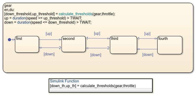
En un gráfico de Stateflow, usted combina estados, transiciones y datos para implementar una máquina de estado finito. Este gráfico de Stateflow presenta un modelo simplificado de la lógica de cambio de marcha del sistema de transmisión automática de cuatro velocidades de un automóvil. El gráfico representa cada la posición de cada marcha por medio de un estado, que se muestra como un rectángulo con la etiqueta first, second, third o fourth. Estos estados, así como las marchas a las que representan, son exclusivos, por lo que solo hay un estado activo en cada momento.

La flecha a la izquierda del diagrama representa la transición predeterminada e indica el primer estado que se activará. Cuando ejecuta el gráfico, este estado aparece resaltado en el área de diseño del gráfico. Las otras flechas indican las posibles transiciones entre los estados. Para definir la dinámica de la máquina de estado, se asocia cada transición a una condición booleana o a un evento activador. Por ejemplo, este gráfico supervisa la velocidad del automóvil y cambia de marcha cuando la velocidad supera un umbral fijo. Durante la simulación, el resaltado del gráfico cambia cuando los diferentes estados se activan.

Este gráfico presenta un diseño simple que ignora factores importantes como la velocidad y el par motor. Puede crear un modelo más amplio y realista enlazando este gráfico de Stateflow con otros componentes de MATLAB® o Simulink®. Los siguientes ejemplos describen dos posibles enfoques.
Simular un gráfico como bloque de Simulink con eventos locales
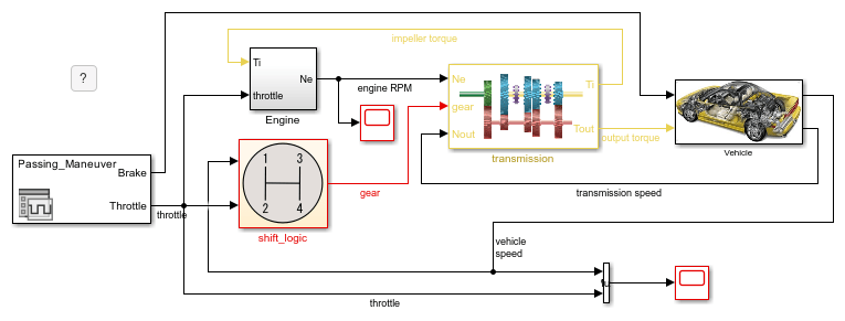
Este ejemplo proporciona un diseño más complejo para un sistema de transmisión automática. El gráfico de Stateflow aparece como un bloque en un modelo de Simulink. Los otros bloques del modelo representan componentes de automoción relacionados. El gráfico interactúa con los otros bloques compartiendo datos a través de las conexiones de entrada y de salida. Para abrir el gráfico, haga clic en la flecha de la esquina inferior izquierda del bloque shift_logic.

Este gráfico combina jerarquía de estados, paralelismo, datos de estado activo, eventos locales y lógica temporal.
Jerarquía: el estado
gear_statecontiene una versión modificada del gráfico de la transmisión automática de cuatro velocidades. El estadoselection_statecontiene subestados que representan los modos operativos de estado estacionario, de aumento de marcha y de reducción de marcha. Cuando las circunstancias requieren un cambio de marcha superior o inferior, estos estados se activan.Paralelismo: los estados paralelos
gear_stateyselection_stateaparecen como rectángulos con un borde discontinuo. Estos estados operan simultáneamente, incluso cuando los subestados dentro de ellos se activan y se desactivan.Datos de estado activo: el valor de salida
gearrefleja la selección de marchas durante la simulación. El gráfico genera este valor a partir del subestado activo engear_state.Eventos locales: en lugar de condiciones booleanas, este gráfico utiliza los eventos locales
UPyDOWNpara activar las transiciones entre marchas. Estos eventos se originan a partir de los comandossendenselection_statecuando la velocidad del automóvil se sale del rango de operación para la marcha seleccionada. La funcióncalc_thde Simulink determina los valores límite para el rango de operación en función de la marcha seleccionada y la velocidad del motor.Lógica temporal: Para evitar una rápida sucesión de cambios de marcha,
selection_stateutiliza el operador de lógica temporalafterpara retrasar la transmisión de los eventosUPyDOWN. El estado transmite uno de estos eventos solo si se requiere un cambio de marcha durante un periodo de tiempo mayor que el tiempo predeterminadoTWAIT.

Para ejecutar una simulación del modelo:
Haga doble clic en el bloque User Inputs. En el cuadro de diálogo de Signal Editor, seleccione un perfil de freno a acelerador predefinido de la lista Active Scenario. El perfil predeterminado es
Passing Maneuver.Haga clic en Run. En el editor de Stateflow, la animación del gráfico resalta los estados activos durante la simulación. Para ralentizar la animación, en la pestaña Debug (Depuración), seleccione
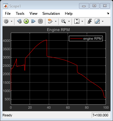
Slowen la lista desplegable Animation Speed (Velocidad de la animación).En los bloques Scope, examine los resultados de la simulación. Cada bloque Scope muestra una gráfica de sus señales de entrada durante la simulación.


Simular un gráfico como bloque de Simulink con condiciones temporales
Este ejemplo ofrece otra alternativa para modelar el sistema de transmisión de un automóvil. El gráfico de Stateflow aparece como un bloque en un modelo de Simulink. Los otros bloques del modelo representan componentes de automoción relacionados. El gráfico interactúa con los otros bloques compartiendo datos a través de las conexiones de entrada y de salida. Para abrir el gráfico, haga clic en la flecha de la esquina inferior izquierda del bloque Gear_logic.

Este gráfico combina jerarquía de estados, datos de estado activo y lógica temporal.
Jerarquía: este modelo coloca el gráfico de transmisión automática de cuatro velocidades dentro de un superestado
gear. El superestado supervisa el vehículo y las velocidades del motor y activa los cambios de marcha. Las acciones que aparecen en la esquina superior izquierda de la marcha de estado determinan los umbrales operativos para la marcha seleccionada y los valores de las condiciones booleanasupydown. La etiquetaen,duindica que las acciones de estado se ejecutan la primera vez que el estado se activa (en=entry) y en cada unidad de tiempo subsiguiente mientras el estado esté activo (du=during).Datos de estado activo: el valor de salida
gearrefleja la selección de marchas durante la simulación. El gráfico genera este valor a partir del subestado activo engear.Lógica temporal: Para evitar una rápida sucesión de cambios de marcha, las condiciones booleanas
upydownutilizan el operador de lógica temporaldurationpara controlar la transición entre marchas. Las condiciones son válidas cuando la velocidad del automóvil se mantiene fuera del rango de operación para la marcha seleccionada durante un periodo de tiempo mayor que tiempo predeterminadoTWAIT(medido en segundos).

Para ejecutar una simulación del modelo:
Haga doble clic en el bloque User Inputs. En el cuadro de diálogo de Signal Editor, seleccione un perfil de freno a acelerador predefinido de la lista Active Scenario. El perfil predeterminado es
Passing Maneuver.Haga clic en Run. En el editor de Stateflow, la animación del gráfico resalta los estados activos durante la simulación. Para ralentizar la animación, en la pestaña Debug (Depuración), seleccione
Slowen la lista desplegable Animation Speed (Velocidad de la animación).En el bloque Scope, examine los resultados de la simulación. El bloque Scope muestra una gráfica de la marcha seleccionada durante la simulación.

Próximos pasos
Para obtener más información sobre los gráficos de Stateflow, siga los siguientes pasos del tutorial: