Triple-Axis Tilt Calculation Using LIS3DH FIFO Data Ready Interrupt
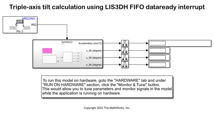
This example shows how to use the FIFO data ready interrupt of LIS3DH linear accelerometer connected to an Arduino® board to sense the tilt of the sensor. This is done using a downstream function-call subsystem that reads acceleration values from FIFO buffer sensor.
The sensor block is placed inside the downstream function-call subsystem. The output of the sensor block is sent to a MATLAB Function block where the data is averaged, and tilt is calculated.
For more information on tilt sensing using accelerometer values, see Using an Accelerometer for Inclination Sensing.
Supported Arduino Hardware
Arduino Due
Arduino Leonardo
Arduino Mega 2560
Arduino Mega ADK
Arduino Micro
Arduino MKR1000
Arduino MKR WIFI 1010
Arduino MKR ZERO
Arduino Nano 3.0
Arduino Robot Control Board
Arduino Robot Motor Board
Arduino Uno
Arduino Nano 33 IoT
Prerequisites
Before you start this example, complete the Get Started with Arduino Hardware example.
Required Hardware
Supported Arduino board
LIS3DH sensor
USB cable
Breadboard wires
Hardware Connection
Connect the INT1 pin of the LIS3DH sensor to pin 3 on the Arduino board.
Connect the SDA, SCL, 3.3V, and GND pin of the Arduino board to the respective pins on the LIS3DH sensor.
Hardware Configuration in the Model
Open the arduino_lis3dh_tiltdetection_fifointerrupt Simulink model.
The model is preconfigured to work with Arduino Mega 2560. If you are using a different Arduino board, change the hardware board by performing the following steps:
1. Navigate to Modeling > Model Settings to open the Configuration Parameters dialog box.
3. Open the Hardware Implementation pane, and from the Hardware board list, select the type of Arduino board that you are using.
3. Click Apply. Click OK to close the dialog box.
Configure the FIFO Data Ready Interrupt on LIS3DH for Interrupt Service Routine (ISR)
1. In the External interrupt handler area of the model, double-click the External Interrupt block, and ensure that the value of Pin number parameter is set to 3, which is same as the Arduino pin that is connected to INT1 pin on LIS3DH sensor. If required, you can change the pin. For example, if you connect INT1 to another pin that supports External Interrupt on the Arduino board.
2. The LIS3DH sensor block is placed in the downstream function call-sub system. The output of the block is connected to MATLAB® function block. The FIFO data acquired by the MATLAB function is averaged, and tilt of each axis is calculated.
3. In AVR targets, for the I2C calls to work from within ISR, place sei(); inside the ISR. The sei() is added to the model using System Output block. The sei() is guarded to be included only for AVR targets and not the ARM targets.
4. Ensure that the Generate data ready interrupt on INT1 pin parameter is selected, and also ensure that FIFO is enabled and Number of samples to read from FIFO (1-32) is provided. In this example, data update is expected at 100 Hz (the specified ODR) and Number of samples to read from FIFO is 10.

Initiate Monitor and Tune Action for the Model
During Monitor and Tune action, the model is deployed as a C code on the hardware. The code obtains real-time data from the hardware. The data acquisition and parameter tuning are done while the application is running on the hardware.
Note: Ensure that the Arduino board you are using has sufficient memory to run the application on hardware. The boards such as Arduino Uno, which has low memory, might not support this application.
1. On the Hardware tab, in the Mode section, select Run on board (External Mode) and then click Monitor & Tune.
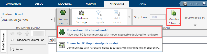
The lower-left corner of the model window displays status while Simulink prepares, downloads, and runs the Simulink model on the hardware. During simulation, the pin 3 on Arduino generates an interrupt on every rising edge of the signal, which triggers the function-call subsystem.
2. Move the sensor and verify the changing values at each time step by double-clicking the Display blocks in the Display data area of the model.
Select a Web Site
Choose a web site to get translated content where available and see local events and offers. Based on your location, we recommend that you select: United States.
You can also select a web site from the following list
Americas
- América Latina (Español)
- Canada (English)
- United States (English)
Europe
- Belgium (English)
- Denmark (English)
- Deutschland (Deutsch)
- España (Español)
- Finland (English)
- France (Français)
- Ireland (English)
- Italia (Italiano)
- Luxembourg (English)
- Netherlands (English)
- Norway (English)
- Österreich (Deutsch)
- Portugal (English)
- Sweden (English)
- Switzerland
- United Kingdom (English)