Use Ethernet Shield with Arduino Hardware
This example shows how to use Simulink® Support Package for Arduino® hardware to receive and send TCP/IP or UDP messages using an Arduino with an Ethernet Shield.
Supported Hardware
Arduino Leonardo
Arduino Mega 2560
Arduino Mega ADK
Arduino Uno
Arduino Due
Available versions of this example:
Arduino Mega 2560 board:
The provided model is pre-configured for Arduino Mega 2560 and can be run on any of the board listed in the Supported Hardware section by changing the "Hardware board" parameter in the configuration parameters dialog box of the model, as described in Task 1 of this example.
Introduction
Simulink Support Package for Arduino hardware enables you to create and run Simulink models on Arduino board. The target includes a library of Simulink blocks for configuring and accessing Arduino sensors, actuators, and communication interfaces.
In this example you will learn how to create Simulink models receiving TCP/IP or UDP messages from a remote host and sending TCP/IP or UDP messages to a remote host, identified with a unique IP address and port number.
The host model uses the blocks from the Instrument Control Toolbox™ to send and receive TCP/IP or UDP messages to the target hardware.
Prerequisites
We recommend completing the Get Started with Arduino Hardware example.
Required Hardware
To run this example you will need the following hardware:
Supported Arduino board
Ethernet Shield
USB cable
RJ45 cable (Straight/Cross) based on whether connecting to router/PC
Connect Ethernet Shield to Arduino Mega 2560 Board
In this task, you will connect your Ethernet Shield to the Arduino Mega 2560 board.
1. Connect the Ethernet Shield on the Arduino Mega 2560 board.
2. Connect a USB cable from the PC to the Arduino Mega 2560 hardware.
For more details on connecting the Arduino Mega 2560 to Ethernet Shield, see Connect Arduino Ethernet Shield to Arduino Hardware.
Configure Network Properties for Host Machine and Ethernet Shield
Refer to Configure Network Settings for Arduino Ethernet Shield section of the documentation to configure the IP Address for the host machine and the Ethernet Shield.
Task 1 - Configure Simulink Model for Supported Arduino Hardware
You will perform this task if your Arduino board is not Arduino Mega 2560 hardware.
In this task, you will configure the model for the supported Arduino board.
1. In your Simulink model, click Simulation > Model Configuration Parameters to open Configuration Parameters dialog box.
2. Select the Hardware Implementation pane and select your required Arduino hardware from the Hardware board parameter list. Do not change any other settings.
3. Click OK.
Task 2 - Sending TCP/IP data with Arduino and Ethernet Shield
This example shows how to use Simulink Support Package for Arduino hardware to send TCP/IP messages using an Arduino board with an Ethernet Shield.
Models involved in the demo
1. Target model running on the Arduino hardware: arduinomega2560_tcpsend
2. Simulink host model: arduinotcp_hostreceive
Run the Model configured for the target on the hardware
1. Open the arduinomega2560_tcpsend Simulink model.

2. Perform Task 1 if your Arduino board is not Arduino Mega 2560 hardware.
3. On the Hardware tab of the Simulink model, in the Mode section, select Run on board and then click Build, Deploy & Start.
Run the host model to receive data from the target model
1. Open the arduinotcp_hostreceive Simulink model.

Double-click on the TCP/IP Receive block. Make sure that the port number is matching the Ethernet shield settings specified earlier to ensure that the data is received from the correct target hardware.
2. In the Simulation tab of the Simulink model, click Run. The scope should display the data being sent from the target hardware.
Task 3 - Receiving TCP/IP Data with Arduino and Ethernet Shield
This task shows how to use Simulink Support Package for Arduino hardware to receive TCP/IP messages using an Arduino board with an Ethernet Shield.
Models involved in the demo
1. Target model running on the Arduino Mega 2560: arduinomega2560_tcpreceive
2. Simulink host model: arduinotcp_hostsend
Run the model configured for the target on the hardware
1. Open the arduinomega2560_tcpreceive Simulink model.

2. Perform Task 1 if your Arduino board is not Arduino Mega 2560 hardware.
3. On the Hardware tab of the Simulink model, in the Mode section, select Run on board and then click Build, Deploy & Start.
Run the host model to send data to the target model
1. Open the arduinotcp_hostsend Simulink model.

Double-click on the TCP/IP Send block. Make sure that the IP address and port number are matching the Ethernet shield settings specified earlier to ensure that the data is sent to the correct target hardware.
2. The target model running on Arduino hardware will receive data from TCP/IP and send it back to the serial port for monitoring and debugging. You can use a serial monitor or hyperterminal on the host machine to watch the serial data coming back from the target.
3. In the Simulation tab of the Simulink model, click Run to start running the host model.
4. At this point, TCP/IP data is sent from the host to the target and serial data is sent back from the target to the host. You should be able to see the serial data on the host using a serial monitor or hyperterminal.
Task 4 - Sending UDP Data with Arduino and Ethernet Shield
This example shows how to use Simulink Support Package for Arduino hardware to send UDP messages using an Arduino Mega 2560 board with an Ethernet Shield.
Models involved in the demo
1. Target model running on the Arduino hardware: arduinomega2560_udpsend
2. Simulink host model: arduinoudp_hostreceive
Run the Model configured for the target on the hardware
1. Open the arduinomega2560_udpsend Simulink model.

2. Perform Task 1 if your Arduino board is not Arduino Mega 2560 hardware.
3. On the Hardware tab of the Simulink model, in the Mode section, select Run on board and then click Build, Deploy & Start.
Run the host model to receive data from the target model
1. Open the arduinoudp_hostreceive Simulink model.

Double-click on the UDP Receive block. Make sure that the port number is matching the Ethernet shield settings specified earlier to ensure that the data is received from the correct target hardware.
2. In the Simulation tab of the Simulink model, click Run. The scope should display the data being sent from the target hardware.
Task 5 - Receiving UDP Data with Arduino and Ethernet Shield
This task shows how to use Simulink Support Package for Arduino hardware to receive UDP messages using an Arduino board with an Ethernet Shield.
Models involved in the demo
1. Target model running on the Arduino hardware: arduinomega2560_udpreceive
2. Simulink host model: arduinoudp_hostsend
Run the model configured for the target on the hardware
1. Open the arduinomega2560_udpreceive Simulink model.

2. Perform Task 1 if your Arduino board is not Arduino Mega 2560 hardware.
3. On the Hardware tab of the Simulink model, in the Mode section, select Run on board and then click Build, Deploy & Start.
Run the host model to send data to the target model
1. Open the arduinoudp_hostsend Simulink model.
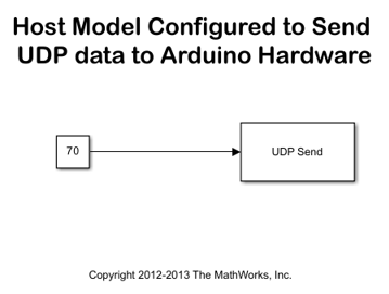
Double-click on the UDP Send block. Make sure that the IP address and port number are matching the Ethernet shield settings specified earlier to ensure that the data is sent to the correct target hardware.
2. The target model running on Arduino hardware will receive data from UDP and send it back to the serial port for monitoring and debugging. You can use a serial monitor or hyperterminal on the host machine to watch the serial data coming back from the target.
3. In the Simulation tab of the Simulink model, click Run to start running the host model.
4. At this point, UDP data is sent from the host to the target and serial data is sent back from the target to the host. You should be able to see the serial data on the host using a serial monitor or hyperterminal.
Select a Web Site
Choose a web site to get translated content where available and see local events and offers. Based on your location, we recommend that you select: United States.
You can also select a web site from the following list
Americas
- América Latina (Español)
- Canada (English)
- United States (English)
Europe
- Belgium (English)
- Denmark (English)
- Deutschland (Deutsch)
- España (Español)
- Finland (English)
- France (Français)
- Ireland (English)
- Italia (Italiano)
- Luxembourg (English)
- Netherlands (English)
- Norway (English)
- Österreich (Deutsch)
- Portugal (English)
- Sweden (English)
- Switzerland
- United Kingdom (English)