Multiple Channel Input and Output Operations
For multiple input multiple output (MIMO) operations, you can use multichannel radios or single channel radios bundled together.
About MIMO Mode
You can use MIMO operations to help achieve better performance in your communications system. For example, space-time block coding can increase the signal-to-noise ratio (SNR) and spatial multiplexing can increase data rates.
To prepare waveforms for MIMO mode, see MIMO Techniques.
Note
The SDRu transmitter and receiver transmit signals through the TX/RX port and receives signals through the RX2 port.
Perform MIMO Operations with USRP System Objects
These examples shows how to use a comm.SDRuTransmitter or comm.SDRuReceiver
System object™ to transmit or receive data on multiple channels.
Transmit over Multiple Channels with SDRu Transmitter
Create an SDRu transmitter System object for a USRP radio that supports MIMO operations.
tx = comm.SDRuTransmitter(Platform="N310");Set the ChannelMapping property to indicate that all four channels are in use.
tx.ChannelMapping = [1 2 3 4]
tx =
  comm.SDRuTransmitter with properties:

                 Platform: 'N310'
                IPAddress: '192.168.10.2'
           ChannelMapping: [1 2 3 4]
          CenterFrequency: 2.4500e+09
    LocalOscillatorOffset: 0
                     Gain: 8
                PPSSource: 'Internal'
        EnableTimeTrigger: false
              ClockSource: 'Internal'
          MasterClockRate: 125000000
      InterpolationFactor: 512
        TransportDataType: 'int16'
          EnableBurstMode: false
Create a comm.DSPKModulator System object to modulate the transmitted signals.
mod = comm.DPSKModulator(BitInput=true);
Generate two sets of modulated random data and transmit the data on two channels.
for i = 1:5
   data1 = randi([0 1],3e4,1);
   modSignal1 = mod(data1);
   data2 = randi([0 1],3e4,1);
   modSignal2 = mod(data2);
   data3 = randi([0 1],3e4,1);
   modSignal3 = mod(data3);
   data4 = randi([0 1],3e4,1);
   modSignal4 = mod(data4);
   tx([modSignal1 modSignal2 modSignal3 modSignal4]);
end
Release the System object.
release(tx);
Receive over Multiple Channels with SDRu System Object
Create an SDRu receiver System object for a USRP radio that supports MIMO operations.
rx = comm.SDRuReceiver(Platform="N310");Set the ChannelMapping property to indicate that all four channels are in use.
rx.ChannelMapping = [1 2 3 4]
rx =
  comm.SDRuReceiver with properties:

                 Platform: 'N310'
                IPAddress: '192.168.10.2'
           ChannelMapping: [1 2 3 4]
          CenterFrequency: 2.4500e+09
    LocalOscillatorOffset: 0
                     Gain: 8
                PPSSource: 'Internal'
        EnableTimeTrigger: false
              ClockSource: 'Internal'
          MasterClockRate: 125000000
         DecimationFactor: 512
        TransportDataType: 'int16'
           OutputDataType: 'Same as transport data type'
          SamplesPerFrame: 362
          EnableBurstMode: false
Receive data on four channels.
[data,datalength] = rx();
Verify that four sets of data have been received.
isequal(width(data),4)
ans = logical
   1
Release the System object.
release(rx);
Perform MIMO Operations with USRP Simulink Blocks
Transmit over Multiple Channels with SDRu Transmitter Block
The SDRu Transmitter block can accept matrices at the data port. The number of columns is the same as the length of the Channel mapping parameter. If you choose to use the optional input ports for center frequency and local oscillator offset, the ports can accept scalars or row vectors of the same length as the Channel mapping parameter.
To create a waveform suitable for MIMO transmission, you can use Communications Toolbox™ blocks to create a design similar to this diagram.
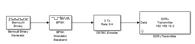
To configure the SDRu Transmitter block, in the block mask:
Set Channel mapping to
[1 2]to use both channels.Set the values for the Center frequency, LO offset, and Gain parameters as two-element row vectors. To apply the same value to both channels, specify a scalar value. For multiple channels, local oscillator (LO) offset must be
0. This requirement is due to a UHD limitation. You can specify LO offset as a scalar (0) or as a vector ([0 0]).Click OK.
Receive from Multiple Channels with SDRu Receiver Block
The SDRu Receiver block can output matrices at the data port. The number of columns is the same as the length of the Channel mapping parameter. If you choose to use the optional input ports for the center frequency, local oscillator offset, and gain, the ports can accept scalars or row vectors of the same length as the Channel mapping parameter.
In Simulink®, design a model that can process multiple received channels , similar to the model in this figure.
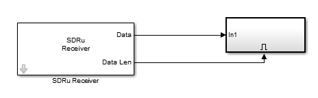

In this example, Channel mapping in the SDRu
Receiver block is defined as [1 2] to indicate that
multiple channels are being used.
To configure the SDRu Receiver block, in the block mask:
Set Channel mapping to
[1 2]to use both channels.Set the values for Center frequency, LO offset, and Gain parameters as two-element row vectors. Alternatively, to apply the same value to both channels, specify a scalar value. For multiple channels, LO offset must be
0. This requirement is due to a UHD limitation. You can specify LO offset as scalar (0) or as a vector ([0 0]).Click OK.
Perform MIMO Operations Bundling Multiple Radios
Bundle Multiple Radios
To perform MIMO operations involving more channels than a single radio can support, you must bundle multiple radios. Ettus Research™ recommends using a common external clock signal source and pulse-per-second (PPS) signal source to bundle multiple radios to act as one radio with multiple channels.
This figure shows a four channel MIMO configuration realized by bundling two USRP™ X300 radios together on the host PC.
The common external 10 MHz clock signal is required for frequency synchronization of channels across bundled radios. The common external PPS signal is required for timing synchronization of channels across bundled radios.
Receive from Multiple Radios with comm.SDRuReceiver System Object
This example shows how to bundle multiple radios for MIMO operations with a USRP Receiver System object.
Create a comm.SDRuReceiver
System object for a platform that supports MIMO mode. This example uses a USRP
X310
radio.
rxRadios = comm.SDRuReceiver(Platform='X310', ...
  IPAddress='192.168.20.2,192.168.20.3')
rxRadios =

  comm.SDRuReceiver with properties:

                  Platform: 'X310'
                IPAddress: '192.168.20.2,192.168.20.3'
    IsTwinRXDaughterboard: false
           ChannelMapping: 1
          CenterFrequency: 2.4500e+09
    LocalOscillatorOffset: 0
                     Gain: 8
                PPSSource: 'Internal'
        EnableTimeTrigger: false
              ClockSource: 'Internal'
          MasterClockRate: 200000000
         DecimationFactor: 512
        TransportDataType: 'int16'
           OutputDataType: 'Same as transport data type'
          SamplesPerFrame: 362
          EnableBurstMode: false
Set the channel mapping to [1 2 3 4] to
indicate that four channels are in use.
rxRadios.ChannelMapping = [1 2 3 4];
Set the center frequency and gain for each channel. Display the configuration information.
rxRadios.CenterFrequency = [1 1.1 1.2 1.3]*1e9;
rxRadios.Gain = [5 6 7 8];
info(rxRadios)
ans =
  struct with fields:
                    Mboard: {'X310' 'X310'}
                  RXSubdev: {'SBXv3 RX' 'SBXv3 RX' 'SBXv3 RX' 'SBXv3 RX'}
                  TXSubdev: {'SBXv3 TX' 'SBXv3 TX' 'SBXv3 TX' 'SBXv3 TX'}
    MinimumCenterFrequency: [380000000 380000000 380000000 380000000]
    MaximumCenterFrequency: [4.4200e+09 4.4200e+09 4.4200e+09 4.4200e+09]
               MinimumGain: [0 0 0 0]
               MaximumGain: [37.5000 37.5000 37.5000 37.5000]
                  GainStep: [0.5000 0.5000 0.5000 0.5000]
           CenterFrequency: [1.0000e+09 1.1000e+09 1.2000e+09 1.3000e+09]
     LocalOscillatorOffset: 0
                      Gain: [5 6 7 8]
           MasterClockRate: 200000000
          DecimationFactor: 512
        BasebandSampleRate: 390625
Receive the data. Because the System object uses four channels, the matrix returned in data contains four columns.
[data,datalen] = rxRadios();
Release the System object.
release(rxRadios);
Receive from Multiple Radios with SDRu Receiver Block
This example shows how to bundle multiple radios for MIMO operations with an SDRu Receiver block. This example uses two USRP X310 radios.
Open the mask of the SDRu Receiver block.
Set these parameters for reception on multiple radios. Then, click OK.
Set Platform to
X310.Set the IP address to
192.168.20.2,192.168.20.3or192.168.20.2 192.168.20.3to specify the IP addresses of the radios.Set Channel mapping to
[1 2 3 4]. Channel mapping values1and2of the bundled radio refer to channels 1 and 2 of the radio with IP address 192.168.20.2. Channel mapping values3and4of the bundled radio refer to channels 1 and 2 of the radio with IP address 192.168.20.3.Set Center frequency (Hz) to
[1 1.1 1.2 1.3]*1e9. Alternatively, to apply the same value to all channels, specify a scalar value.Set Gain (dB) to
[5 6 7
                    8]
. Alternatively, to apply the same receiver gain value to all channels, specify a scalar value.

The SDRu Receiver block outputs a matrix at its data port. The number of columns of the output matrix equals the length of the Channel mapping parameter.