MultiPort Packet Based USRP Targeting
This example shows how to deploy a multi-port packet based algorithm using the NI™ USRP™ radio targeting workflow. The example starts with a Simulink® model of an algorithm that applies an FFT to samples received from the radio and plots the output in MATLAB®, then takes you through steps to deploy the design on your software-defined radio (SDR).
Introduction
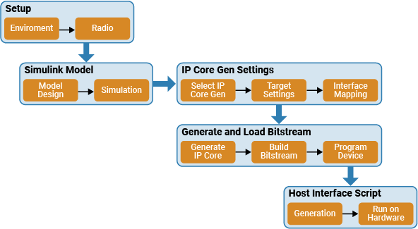
In this example, you follow a step-by-step guide to generate a bitstream from the model in Simulink and deploy it on an NI USRP radio using a generated MATLAB host interface script. The model is an algorithm that generates a complex sine wave for transmission to radio, performs an FFT on the received samples from radio, and plots the output in Simulink. This diagram shows the workflow.
Set Up Environment and Radio
To use the NI USRP targeting workflow, you must install and configure additional toolboxes, support packages, and third-party tools. For more information, see Installation for Targeting NI USRP Radios.
Call the radioConfigurations
savedRadioConfigurations = radioConfigurations;
Select the radio to use with this example. If no radio configurations are available, use the radioSetupWizard
savedRadioConfigurationNames = [string({savedRadioConfigurations.Name})];
radio = savedRadioConfigurationNames(1);
Open the Model
The Simulink model in this example is a hardware generation model of an SDR algorithm. Using the HDL Code tab in the Simulink Toolstrip or the HDL Workflow Advisor, you can generate a custom HDL IP core from the model, then generate a bitstream and load it onto the FPGA on your radio. You can then generate a host interface script that provides the MATLAB code you need to interact with the hardware.
Open the model from MATLAB.
modelname = 'wtMultiPortPacketBasedUSRPTargetingExampleSL';
open_system(modelname);

The top-level structure of the model includes multiple subsystems. The TxRx subsystem is used for HDL code generation, and the others are for simulating radio I/O and host interface.
The
Radio RF SourceandRadio RF Sinksubsystems simulate the behavior of the radio connections to the DUT.The
TxRxsubsystem generates a complex sine wave for transmission and performs an FFT on the received samples. This subsystem is the DUT.The
PL DDR Buffersubsystem and pass through registers simulate the behavior of the PL DDR buffer connection on the radio, which receives output data from the DUT.The
Process Frame,BinNumber2Frequency, andCalculate NCO Incrementsubsystems simulate the generated MATLAB host interface script.
Simulate Hardware Generation Model
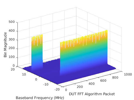
To confirm the behavior of the model, simulate the system by running the model. The output of the simulation is a plot of the bin magnitudes from the FFT algorithm which is run on the data samples transmitted from the DUT.

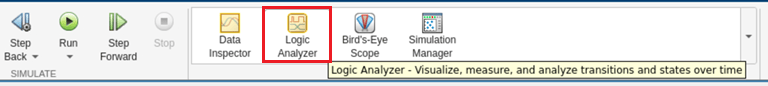
To review the behavior of the DUT streaming ports, open the Logic Analyzer from the Apps tab in Simulink.
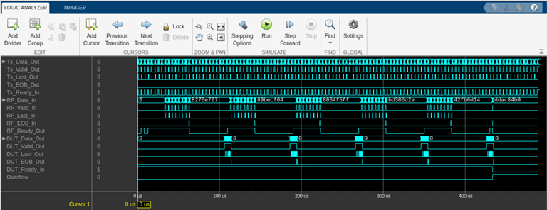
The transitions across the full simulation time are shown in the diagram. Observe the operation of the DUT at a high level.
When the radio requests samples by setting Tx_Ready_In high, the DUT provides data for transmission on Tx_Data_Out and sets Tx_Valid_Out high.
DUT_Ready_In is high when the PL DDR buffer is not full. The DUT sets RF_Ready_Out when the internal FFT block is ready to receive data from the radio. After some time, the radio sends samples to the DUT on RF_Data_In . The DUT receives a full frame of samples, then sets RF_Ready_Out low. The frame is processed by the DUT then output on DUT_Data_Out . RF_Ready_Out is set high because the DUT is ready for new samples. This is repeated in the simulation until the PL DDR buffer is full.
Open the TxRx subsystem.
open_system([modelname '/TxRx']);

This contains the Generate TX Tone and Compute RX Spectrum Magnitudes subsystems.
Open the Generate TX Tone subsystem.
open_system([modelname '/TxRx/Generate TX Tone'])

The Generate TX Tone subsystem generates a complex sine wave using the NCO block. It is controlled with following signals.
The TX_Increment_In port controls the frequency of the generated sine wave. It is configured as a write register from host interface.
The Tx_Ready_In port controls the rate of the valid input of the NCO. It is configured as the ready input signal of the transmit streaming interface. The radio connection uses the ready signal to request data samples from the DUT at the specified sample rate. To set the sample rate, open the Model Explorer from the Modeling options in the HDL Code tab in the Simulink Toolstrip. The default is 61.44e6.
The TransmitTone port enables the transmission.
The Tx_Data_Out port specifies the generated data samples intended for transmission to the radio. Each sample is a complex 16-bit integer from the NCO and concatenated as 32-bit integer in the
BitCatsubsystem.The Tx_Valid_Out port controls the data rate of the tx data. This data rate must match the Tx_Ready_In port.
The Tx_last_Out port indicates the end of a streaming packet. It is true for every 256 valid samples.
The TX_EOB_Out port indicates the end of a contiguous burst of samples. It is signaled when TransmitTone signal is false.
Use the logic analyzer to examine the signals that make up the streaming interface connection to the radio front end.
The timing diagram demonstrates that the Generate TX Tone subsystem responds to the ready signal from the radio. The radio requests samples in packets of 256 samples. The sample rate used in the diagram is 61.44 Ms/s and the MCR (the rate at which the DUT is clocked) is 245.76 MHz. The sample rate is one quarter of the MCR, so the ready signal is high for one sample in every four.
The timing diagram also demonstrates how the Generate TX Tone subsystem asserts the last output at the end of each packet of 256 samples. Failing to assert the last output signal would delay the data packet. In extreme cases, this will lead to an overflow of internal buffers.

Open the Compute RX Spectrum Magnitudes subsystem.
open_system([modelname '/TxRx/Compute RX Spectrum Magnitudes'])

The Compute RX Spectrum Magnitudes subsystem performs an FFT on the samples received from the radio, and then plots the output in MATLAB. It is controlled with following signals.
The Data_In port specifies the data samples from the radio connection. Each sample is a 32-bit integer, which is sliced into a complex 16-bit integer in the
BitSlicesubsystem.The Valid_In port signals the rate of the data in from the radio according to the sample rate.
The EOB_In port indicates the last packet of the stream of contiguous samples. It is true for the duration of the last packet.
The Last_In port is true for the last sample of each packet. The EOB_In and Last_in ports are input to an AND gate. The output of this is true on the last sample of the last packet, indicating the end of the stream of contiguous samples. If the FFT is still ready for new samples after this goes high, this indicates an incomplete frame, which would result in a discontiguity. Therefore, the output signal from the AND gate is used to reset the Simulink block which erases the incomplete frame.
The ProcessFrames port is a write register used to enable or disable the algorithm. When de-asserted, it resets the FFT Simulink block and asserts EOB_Out to prevent stale samples from being received when the system is re-enabled.
The Ready_Out port when false exerts back pressure on the streaming connection with the radio. If samples are received from the radio when Ready_out is false they are buffered in the endpoint buffer. If the buffer is full this indicated an overflow and the radio stops streaming new samples. It is asserted true when the ProcessFrames register is true, the upstream PL DDR buffer is ready as indicated by the Ready_In port, and the FFT Simulink block is ready for new samples.
The MaxBin port is a read register which gives the index of the largest magnitude bin in the most recent FFT packet as computed in the
Hold Largest Magnitude Bin Indexsubsystem.The Data_Out port specifies the data samples at the output of the algorithm as unsigned 32-bit integers. Each sample contains a signed 17 bit integer bin magnitude computed by the Complex to Magnitude-Angle Simulink block and uses the highest bit to signal the start of each FFT packet.
The Valid_Out port controls the rate of the output data and is high when the output of the Complex to Magnitude-Angle Simulink block is valid and the ProcessFrames input port is true.
The EOB_Out port indicates the end of a packet from the FFT and is asserted by the FFT Simulink block end signal or when ProcessFrames input port is de-asserted.
The Last_Out port indicates the end of streaming packet. It is high for one sample every 256 valid samples and at the end of the full FFT packet.
Use the logic analyzer to examine the signals that make up the streaming interface connection from the radio front end. This timing diagram shows the last packet of 256 samples which, together with the previous packets, constitute a single contiguous burst of samples at the requested sample rate. Since the number of samples in the burst is the same as the FFT length, the RF_Ready_Out signal is deasserted after the last sample of the last packet while the frame of samples is processed. The end of burst signal on RF_EOB_In is high for the duration of the last packet.

Finally, use the logic analyzer to examine the signals that make up the DUT streaming interface connection to the PL DDR buffer. This timing diagram shows a packet of data from the DUT algorithm which is buffered in the PL DDR buffer then read from the host interface. The length of the packet corresponds to the FFT length. To ensure the data from the DUT is sent into the PL DDR buffer, the DUT_Last_Out signal is asserted every 256 samples and the end of burst is asserted at the end of the DUT data packet.

Customize Simulation to Radio Device
By default, the model simulates a sample rate of 61.44 MS/s with an MCR of 245.76 MHz for an NI USRP N320 radio. To customize the behavior to better simulate for your hardware, set the MCR to a valid value for your radio. For details, see Baseband Sample Rate in NI USRP Radios.
From the Modelling tab in the Simulink Toostrip, select Model Explorer. Open Model Workspace under the model hierarchy.
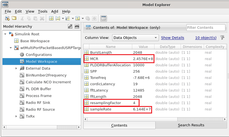
Set the
MCRto a supported MCR for your radio.Set the
sampleRateto a supported resampled rate of theMCRvalue.Set the
resamplingFactortoMCRdivided bysampleRate.
Set the toneFreq to the arbitrary complex tone frequency that you want to transmit from the DUT for the simulation. The default value is -7.68 MHz, which is an exact division of sampleRate and in quadrature phase. You can also change the simulated PL DDR buffer allocation by setting the PLDDRBufferAllocation variable or the simulated burst length by setting the BurstLength variable.
Generate IP Core
When you are satisfied with the simulated behavior of the model, you can proceed to integrate your design into a custom IP core by generating HDL code and mapping the model inputs and outputs to the hardware interfaces.
First, use the hdlsetuptoolpath (HDL Coder) function to set up the Xilinx® tool chain.
>> hdlsetuptoolpath('ToolName','Xilinx Vivado','ToolPath','/opt/Xilinx/Vivado/2019.1/bin');
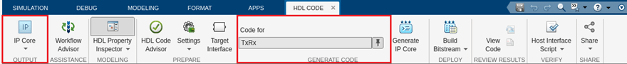
From the Apps tab in the Simulink Toostrip, select HDLCoder. Open the HDL Code tab and follow these steps:
Ensure the the
TxRxsubsystem is pinned in the Code for option. To pin this selection, select theTxRxsubsystem in the Simulink model and click the pin icon.Select IP Core as the OUTPUT > IP Core option.
Configure HDL Code Generation
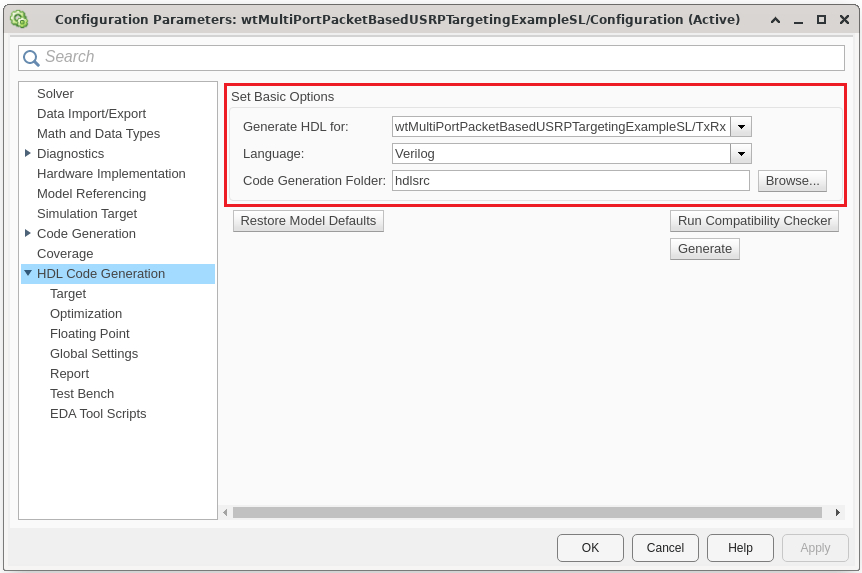
Click Settings in the HDL Code tab to open the Configuration Parameters window.
In the basic options of the HDL Code Generation panel, ensure that Language is set to Verilog. By default, HDL Coder generates the Verilog files in the hdlsrc folder. You can select an alternative location. If you make any changes, click Apply.
Configure HDL Code Generation Target
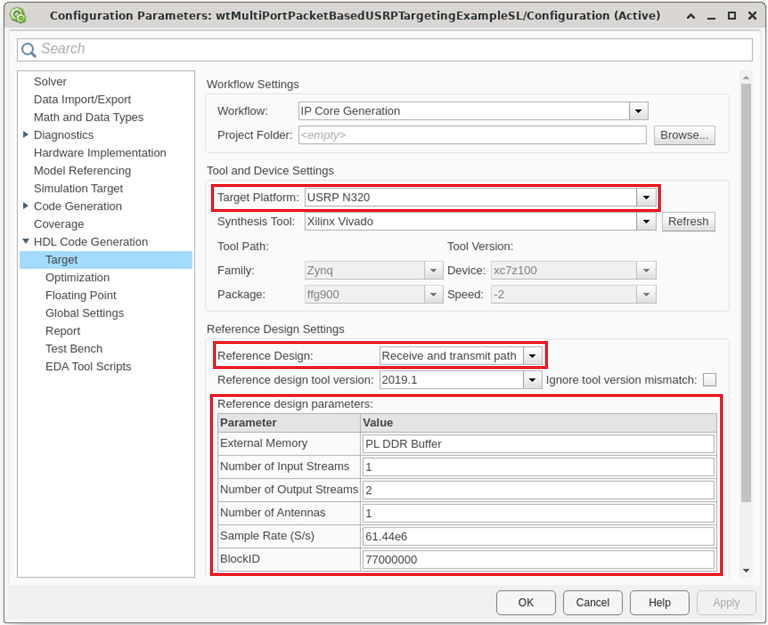
In the HDL Code Generation > Target > Workflow settings, click browse and select the project folder in which you want to save the generated project files.
In the HDL Code generation > Target > Tool and Device settings, set Target Platform to
USRP N320. If you are using a different USRP radio, select the corresponding target platform and adjust the reference design parameters accordingly.In the HDL Code generation > Target > Reference Design settings, set Reference Design to
Receive and transmit pathand set the reference design parameters with the following values:
External Memory - Set to
PL DDR Bufferto stream samples through the memory buffer from FPGA. This setting ensures contiguous samples between MATLAB and the FPGA.Number of Input Streams - Set to
1because the DUT is connected to one data input stream.Number of Output Streams - Set to
2because the DUT is connected to two data output streams.Number of Antennas - Set to
1because the DUT has one radio receive and transmit channel.Sample Rate (S/s) - Set to
61.44e6, which is the supported value for the USRP N320. For a list of supported sample rates, see Baseband Sample Rate in NI USRP Radios.BlockID - Set this to
77000000, which is a 32-bit hexadecimal number.
Click Apply.
Configure Target Interface
In the HDL Code tab, click Target Interface to open the IP Core editor.
In the Interface Mapping tab, reload the port interface mapping options by clicking the
Reload IP core settings and interface mapping table from modelicon.
For more information, see Configure Hardware Interfaces.
Assign the data, valid, ready, last, and eob signals.
Assign the input registers of the DUT as write registers.
Assign the output registers of the DUT as read registers.
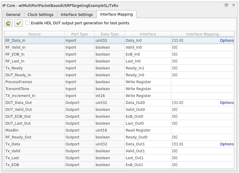
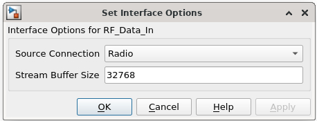
Each data input and output port has an options menu. For the RF_Data_In options, set the source connection to Radio. The input samples to the DUT are received from the radio. Set the stream buffer size to 32768, which is the default setting. The buffer size must be a power of two to ensure optimal use of the FPGA RAM resources. The buffer size is specified in terms of the number of samples, with each sample having a size of 8 bytes.
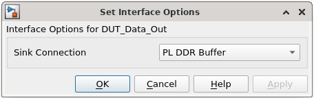
For the DUT_Data_Out options, select the PL DDR Buffer as the sink connection. The DUT streams samples to MATLAB for post-processing through the on-board radio memory buffer.
For the TX_Data options, select the Radio as the sink connection. The DUT transmits samples to radio.

Click the Validate IP core settings and interface mapping icon to validate the interface mapping.
Click Generate IP Core to generate the HDL code and IP Core.
Generate and Load Bitstream
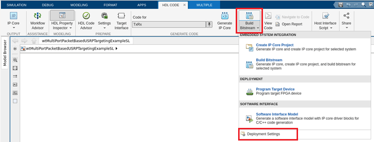
To generate a bitstream from the IP core, first open the deployment settings from the Build Bitstream dropdown and ensure that the Run build process externally option is selected. This setting is the default and it ensures that the bitstream build executes in an external shell. The external shell allows you to continue using MATLAB while building the FPGA image.

Click Build Bitstream to create a Vivado® IP core project and build the bitstream. After the basic project checks complete, the Diagnostic Viewer displays a Build Bitstream Successful message along with warning messages. However, you must wait until the external shell displays a successful bitstream build before moving to the next step. Closing the external shell before this terminates the build. The bitstream for this project generates with the name n3xx.bit and is located in the build_N310_HG/build_N310_HG folder of the working folder after a successful bitstream build.
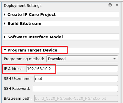
Open the Deployment Settings from the Build Bitstream dropdown. In the Program target Device settings, set the IP address. The default is 192.168.10.2. If you changed the IP address from the default when you set up your hardware using the Radio Setup wizard, set the IP Address accordingly. To load the bitstream onto the device, click Program Target Device from the Build Bitstream dropdown.
Alternatively, if you want to load the bitstream outside of this workflow, use the programFPGA function in the generated host interface script.
Generate Host Interface Script
In the HDL Code tab, Host Interface Script generates two MATLAB scripts, gs_wtMultiPortPacketBasedUSRPTargetingExampleSL_interface.m and gs_wtMultiPortPacketBasedUSRPTargetingExampleSL_setup.m, based on the target interface mapping you configured for your IP core.
The gs_wtMultiPortPacketBasedUSRPTargetingExampleSL_interface.m script creates an fpga hardware object for interfacing with your FPGA from MATLAB. It contains MATLAB code connects to your hardware and programs the FPGA. Code samples get you started with running the algorithm on your radio.

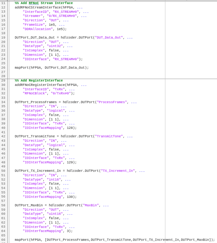
The gs_wtMultiPortPacketBasedUSRPTargetingExampleSL_setup.m script configures the fpga object with the hardware interfaces and ports from your DUT algorithm. It also contains DUT port objects that have the port name, direction, data type, and interface mapping information. It maps these DUT ports to the corresponding interfaces.
Use the generated host interface script as a starting point for deployment. Consider saving the generated script under a unique name and develop your algorithm there to read and write ports. The Host Interface Script button generates the scripts in your working directory.
Run Host Interface Script
For rapid prototyping, customize the host interface script based on your algorithm.
Connect your host computer to the radio using the Radio Setup wizard and create a radio configuration, or use a saved radio configuration that you have already set up. Call the
radioConfigurationsfunction to list all available saved radio configurations.Modify the read and write commands in the interface script file to match your data requirements. Use the modified script interface with your deployed DUT IP core or algorithm running on the target board.
Run the sections of the host interface script to connect to your hardware board, program the FPGA, create an
fpgaobject, and set up the interfaces. The interfaces are set up based on the interface setup function file. You only need to run these sections only once.Run the modified read and write commands and iterate on these commands.
When you have finished prototyping, release the connection to the hardware board.
This example uses an edited script based on the generated host interface script. Open the script for editing.
edit('wtMultiPortPacketBasedUSRPTargetingExampleSL_interface');
The script works with all supported target platforms. Run the script you will generate and transmit a tone using the DUT then receive and visualize the tone over the air by capturing and plotting the output of the DUT FFT algorithm in MATLAB.
After you have iterated and tested the host interface script, you can:
Integrate the script into a testing or verification workflow.
Create a live script and interactively prototype your design.
Manage Host Interface Scripts
You can manage your host interface script files by either updating or regenerates the files. Update host interface script files when you make changes such as modifying parameters, fixing errors. Regenerate host interface script files when you make major changes such as modifying the DUT port mapping, changing the target hardware device vendor, or changing the target software tool. When you regenerate the host interface script files, HDL Coder displays a warning about overwriting the existing files. You can rename your existing files to prevent them from being overwritten.
Related Topics
You can also select a web site from the following list:
Americas
- América Latina (Español)
- Canada (English)
- United States (English)
Europe
- Belgium (English)
- Denmark (English)
- Deutschland (Deutsch)
- España (Español)
- Finland (English)
- France (Français)
- Ireland (English)
- Italia (Italiano)
- Luxembourg (English)
- Netherlands (English)
- Norway (English)
- Österreich (Deutsch)
- Portugal (English)
- Sweden (English)
- Switzerland
- United Kingdom (English)