Basic WLAN Link Modeling
This example shows how to create a basic WLAN link model using WLAN Toolbox™. The example creates an IEEE® 802.11ac™ (Wi-Fi™ 5) [1] VHT packet and passes it through a TGac channel. Then, the example equalizes and decodes the received signal in order to recover the transmitted bits.
Introduction
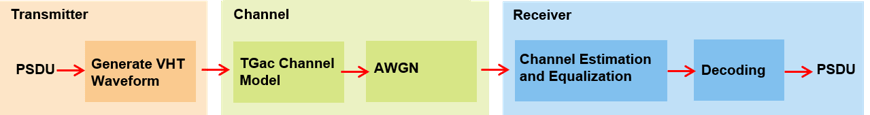
This example shows you how to create a simple transmitter-channel-receiver simulation using WLAN Toolbox. The example implements a VHT transmit and receive link by transmitting a VHT packet through a TGac channel then demodulating and equalizing the symbols. Finally, the example decodes the equalized symbols to recover the transmitted bits. These processing steps are shown in this diagram.
Waveform Generation
This example simulates an 802.11ac VHT transmission. To configure the transmit parameters for the VHT format of the 802.11™ standard, use a wlanVHTConfig object. This example configures the object for a 20 MHz channel bandwidth, modulation and coding scheme (MCS) 5, and a single transmit antenna.
% Create a format configuration object for a SISO VHT transmission
cfgVHT = wlanVHTConfig;
cfgVHT.NumTransmitAntennas = 1;    % Transmit antennas
cfgVHT.NumSpaceTimeStreams = 1;    % Space-time streams
cfgVHT.APEPLength = 4096;          % APEP length in bytes
cfgVHT.MCS = 5;                    % Single spatial stream, 64-QAM
cfgVHT.ChannelBandwidth = 'CBW20'; % Transmitted signal bandwidth
Rs = wlanSampleRate(cfgVHT);       % Sampling rate
Generate a single VHT packet. VHT packets consist of these training, signal and data fields:
Non-HT Short Training Field (L-STF)
Non-HT Long Training Field (L-LTF)
Non-HT Signal (L-SIG) Field
VHT Signal A (VHT-SIG-A) Field
VHT Short Training Field (VHT-STF)
VHT Long Training Field (VHT-LTF)
VHT Signal B (VHT-SIG-B) Field
Data Field
The example generates each field separately, then creates a VHT packet by concatenating them.
The first field in the packet is the L-STF. This field enables the receiver to detect the beginning of the packet. It is also used for automatic gain control (AGC) setting, initial frequency offset estimation, and coarse timing synchronization. To generate the L-STF field in the time domain, use the wlanLSTF function with the configuration object cfgVHT.
lstf = wlanLSTF(cfgVHT);
The L-LTF is used for fine time synchronization, channel estimation and fine frequency offset estimation. To generate the L-LTF in the time domain, use the wlanLLTF function.
lltf = wlanLLTF(cfgVHT);
The L-SIG field carries packet configuration information such as the data rate, the modulation type, and the code rate for the non-HT format. To generate the L-SIG field in the time domain, use the wlanLSIG function.
lsig = wlanLSIG(cfgVHT);
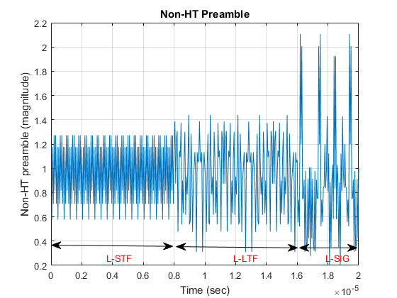
This figure shows the L-STF, L-LTF and L-SIG fields. These fields are common to the VHT, HT-Mixed and non-HT OFDM transmission formats.
nonHTPreamble = [lstf;lltf;lsig]; % Combine the non-HT fields
The example generates the VHT-specific signal and training fields after the non-HT preamble fields. The VHT-SIG-A field provides information that enables the receiver to decode the data payload. The VHT-SIG-A is composed of two symbols, called VHT-SIG-A1 and VHT-SIG-A2. To generate the VHT-SIG-A field in the time domain, use the wlanVHTSIGA function.
vhtSIGA = wlanVHTSIGA(cfgVHT);
The VHT-STF improves the gain control estimation in a MIMO transmission. To generate the VHT-STF field in the time domain, use the wlanVHTSTF function.
vhtstf = wlanVHTSTF(cfgVHT);
The VHT-LTF enables the receiver to estimate the channel between the transmitter and the receiver. Depending on the number of space-time streams, it consists of one, two, four, six, or eight VHT-LTF symbols. To generate the VHT-LTF field in the time domain, use the wlanVHTLTF function.
vhtltf = wlanVHTLTF(cfgVHT);
The VHT-SIG-B field sets the data rate and the length of the data field payload of the transmitted packet. To generate the VHT-SIG-B field in the time domain, use the wlanVHTSIGB function.
vhtSIGB = wlanVHTSIGB(cfgVHT);
Construct the preamble by concatenating the non-HT and VHT preamble fields. The VHT preamble consists of signal and training fields.
vhtPreamble = [nonHTPreamble;vhtSIGA;vhtstf;vhtltf;vhtSIGB];
The wlanVHTData function generates the time-domain VHT data field. The VHT format configuration object cfgVHT specifies the parameters for generating the data field from the PSDU bits. The PSDULength property gives the number of bytes to be transmitted in the VHT data field. Use this property to generate the random PSDU bits txPSDU.
rng(0,'twister') % Initialize the random number generator
txPSDU = randi([0 1],cfgVHT.PSDULength*8,1); % Generate PSDU data in bits
data = wlanVHTData(txPSDU,cfgVHT);

% Construct a VHT waveform by concatenating the VHT preamble and data
% fields
txWaveform = [vhtPreamble;data]; % Transmit VHT PPDU
Alternatively, you can generate the waveform for a given format configuration with a single function call by using the wlanWaveformGenerator function. This function can produce one or more VHT packets. By default, the function applies OFDM windowing to the generated waveform. For more information on OFDM windowing, see the reference page for the wlanWaveformGenerator function.
Channel Impairments
This section simulates the effects of over-the-air transmission. Channel effects and AWGN impair the transmitted signal. This example uses the TGac channel model [2] with delay profile Model-B. For this delay profile, when the distance between transmitter and receiver is greater than or equal to five meters, the model is in Non-Line-of-Sight (N-LOS) configuration. For more information about delay profiles, see wlanTGacChannel.
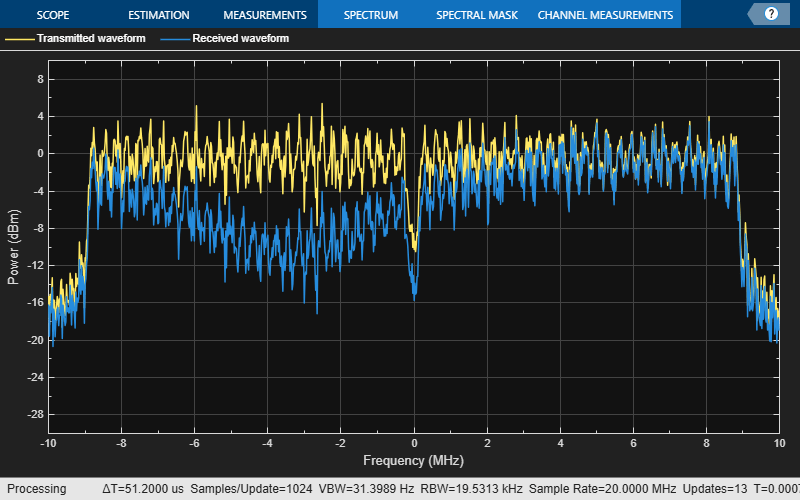
% Parameterize the channel
tgacChannel = wlanTGacChannel;
tgacChannel.DelayProfile = 'Model-B';
tgacChannel.NumTransmitAntennas = cfgVHT.NumTransmitAntennas;
tgacChannel.NumReceiveAntennas = 1;
tgacChannel.LargeScaleFadingEffect = 'None';
tgacChannel.ChannelBandwidth = 'CBW20';
tgacChannel.TransmitReceiveDistance = 5;
tgacChannel.SampleRate = Rs;
tgacChannel.RandomStream = 'mt19937ar with seed';
tgacChannel.Seed = 10;

% Pass signal through the channel. Append zeroes to compensate for channel
% filter delay
txWaveform = [txWaveform;zeros(10,1)];
chanOut = tgacChannel(txWaveform);

snr = 40; % In dBs
rxWaveform = awgn(chanOut,snr,0);

% Display the spectrum of the transmitted and received signals. The
% received signal spectrum is affected by the channel
spectrumScope  = spectrumAnalyzer(SampleRate=Rs, ...
            AveragingMethod='exponential',ForgettingFactor=0.99, ...
            YLimits=[-30 10],ShowLegend=true, ...
            ChannelNames={'Transmitted waveform','Received waveform'});
spectrumScope([txWaveform rxWaveform]);
Channel Estimation and Equalization
In this section, the example extracts the time-domain VHT-LTF from the received waveform. The waveform is assumed to be synchronized to the start of the packet by accounting for the channel filter delay. Demodulate the VHT-LTF and use it to estimate the channel. Use the channel estimate to equalize the received signal.
This example synchronizes the received signal to the start of the packet by compensating for a known channel filter delay. For more information on how to automatically detect and synchronize to a received signal see these examples:
chInfo = info(tgacChannel); % Get characteristic information
% Channel filter delay, measured in samples
chDelay  = chInfo.ChannelFilterDelay;
rxWaveform = rxWaveform(chDelay+1:end,:);
After synchronization, the receiver must extract the individual fields from the received packet. Use the wlanFieldIndices function to return the start and end time-domain sample indices of all fields relative to the first sample in a packet. Use these indices to extract the required fields for further processing.
indField = wlanFieldIndices(cfgVHT);
To extract the VHT-LTF from the received signal, use the start and end indices to generate a vector of indices.
indVHTLTF = indField.VHTLTF(1):indField.VHTLTF(2);
The VHT-LTF enables the receiver to estimate the channel between all space-time streams and receive antennas. Extract the VHT-LTF from the received waveform and demodulated it using the wlanVHTDemodulate function.
demodVHTLTF = wlanVHTDemodulate(rxWaveform(indVHTLTF,:),'VHT-LTF',cfgVHT);
The channel estimate includes the effect of the applied spatial mapping and cyclic shifts at the transmitter for a multi-antenna configuration. The wlanVHTLTFChannelEstimate function returns the channel estimate between all space-time streams and receive antennas.
[chanEstVHTLTF,chanEstSSPilots] = wlanVHTLTFChannelEstimate(demodVHTLTF,cfgVHT);
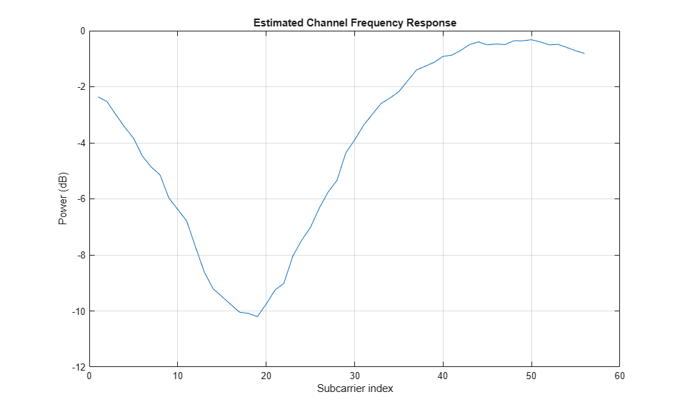
The transmit signal encounters a deep fade as shown in the channel frequency response in the figure below. You can also see the effect of channel fades in the spectrum plot shown previously.
figure
plot(20*log10(abs(chanEstVHTLTF)));
grid on;
title('Estimated Channel Frequency Response');
xlabel('Subcarrier index');
ylabel('Power (dB)');
To extract the data field from the received signal, use the start and end indices for the data field to generate a vector of indices.
indData = indField.VHTData(1):indField.VHTData(2);
rxData = rxWaveform(indData,:);

% Demodulate the VHT data field
sym = wlanVHTDemodulate(rxData,'VHT-Data',cfgVHT);

% Estimate and correct for any phase error
trackedSym = wlanVHTTrackPilotError(sym,chanEstVHTLTF,cfgVHT,'VHT-Data');

% Estimate the noise power in VHT data field
nVar = vhtNoiseEstimate(trackedSym,chanEstSSPilots,cfgVHT);

% Equalize the tracked symbols
[eqSym,csi] = wlanVHTEqualize(trackedSym,chanEstVHTLTF,nVar,cfgVHT,'VHT-Data');

% Recover the transmitted PSDU in the VHT data field
rxPSDU = wlanVHTDataBitRecover(eqSym,nVar,csi,cfgVHT);

% Compare transmit and receive PSDU bits
numErr = biterr(txPSDU,rxPSDU);
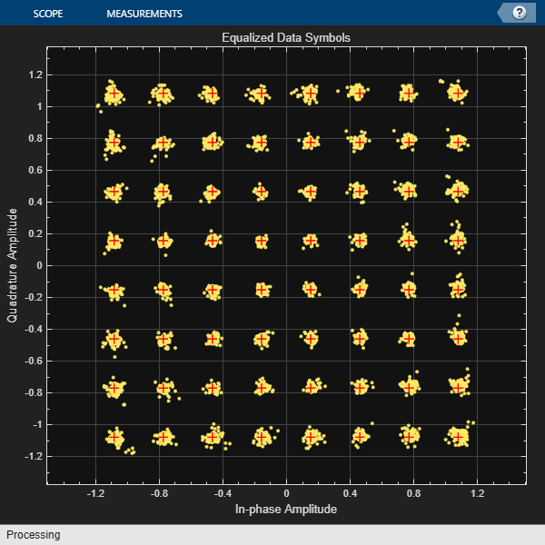
The following plot shows the constellation of the equalized symbols at the output of the wlanVHTDataRecover function compared against the reference constellation. Increasing the channel noise by reducing the SNR value you use with the awgn function increases the spread of the constellation points.
% Plot equalized symbols
constellationDiagram = comm.ConstellationDiagram;
constellationDiagram.ReferenceConstellation = wlanReferenceSymbols(cfgVHT);
% Extract the data indices from the equalized symbols
ofdmInfo = wlanVHTOFDMInfo('VHT-Data',cfgVHT);
eqSymData = eqSym(ofdmInfo.DataIndices,:,:);
% Compare received and reference constellation
constellationDiagram(reshape(eqSymData,[],1));
constellationDiagram.Title = 'Equalized Data Symbols';
Selected Bibliography
IEEE Std 802.11™-2020. IEEE Standard for Information Technology - Telecommunications and Information Exchange between Systems - Local and Metropolitan Area Networks - Specific Requirements - Part 11: Wireless LAN Medium Access Control (MAC) and Physical Layer (PHY) Specifications.
Breit, G., H. Sampath, S. Vermani, et al. TGac Channel Model Addendum. Version 12. IEEE 802.11-09/0308r12, March 2010.
See Also
wlanVHTConfig | wlanWaveformGenerator | wlanTGacChannel