Dynamic Bandwidth Channel Access in Wi-Fi Networks
This example shows how to configure and simulate dynamic bandwidth channel access (DBCA) in a Wi-Fi® scenario consisting of two basic service sets (BSSs).
Using this example, you can:
Create and configure two BSSs, each consisting of a Wi-Fi access point (AP) and a station (STA).
Configure the primary 20 MHz channel for each BSS.
Configure bidirectional application traffic between the AP and STA in each BSS.
Add a TGax fading channel model between the nodes.
Simulate the scenario, and visualize the packet communication in the time and frequency domains for the APs and the STAs.
Capture and view the application layer (APP), medium access control (MAC), and physical layer (PHY) statistics for each node.
Compute the throughput (in Mbps) of each BSS.
Dynamic Bandwidth Channel Access
The DBCA capability optimizes use of the available channel spectrum by adjusting the bandwidth dynamically based on current network conditions and requirements. This figure shows how DBCA enables an STA to use 20 MHz, 40 MHz, or 80 MHz of channel bandwidth for data transmission depending on the availability of the secondary channels.
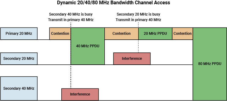
In DBCA, the enhanced distributed channel access function (EDCAF) contends in the contention window (CW) to access the primary 20 MHz channel. Before transmitting a PHY convergence procedure (PLCP) protocol data unit (PPDU), the STA waits for the arbitration interframe spacing (AIFS) period, and then selects a random backoff time, which is an integer in the range [0, CW], where CW is the length of the contention window. Note that the transmission history of PPDUs influences the CW value. Initially, the CW value is CWmin, the minimum contention window. Each CW value corresponds to a backoff stage, which represents the waiting period before data transmission. At each slot boundary, the EDCAF monitors the clear channel assessment (CCA) state of the primary 20 MHz channel. If the primary channel is idle at the end of the backoff time, the STA checks the secondary 20 MHz channel. If the secondary channel is also idle, the STA transmits the PPDU using 40 MHz of bandwidth, consisting of the primary and secondary 20 MHz channels. Otherwise, it uses only the primary channel for data transmission. In the above figure, observe that the secondary 40 MHz and secondary 20 MHz channels are occupied. Consequently, the STA transmits the PPDU using the primary 40 MHz and primary 20 MHz channels.
The DBCA method uses frequency resources more effectively than a static approach. In the static method, an STA must wait for all secondary channels to become available before transmitting data. To ensure the receiver is aware of the transmission channel, include the primary channel within the 20 MHz or 40 MHz bandwidth transmissions [1].
DBCA Wi-Fi Scenario
The example configures and simulates DBCA in a Wi-Fi scenario.
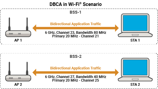
The scenario involves two BSSs: BSS-1 and BSS-2.
BSS-1 — Consists of AP1 and STA1 operating in the 6 GHz frequency band on channel 23. The channel bandwidth is 80 MHz. The primary 20 MHz channel of BSS-1 is channel 21.
BSS-2 — Consists of AP2 and STA2 operating in the 6 GHz frequency band on channel 27. The channel bandwidth is 40 MHz. The primary 20 MHz channel of BSS-2 is channel 25.
In both the BSSs, APs and STAs transmit bidirectional application traffic between them. This figure shows the channel and bandwidth configuration of each BSS.
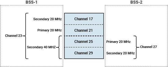
BSS-1 operates on channel 23, which consists of these four 20 MHz channels: 17, 21, 25, and 29. BSS-1 uses channel 17 as the secondary 20 MHz channel, and channel 25 and channel 29 as the secondary 40 MHz channels. BSS-2 operates on channel 27, which consists of these two 20 MHz channels: 25 and 29. BSS-2 uses channel 29 as the secondary 20 MHz channel.
Configure Simulation Parameters
Set the seed for the random number generator to 1. The seed value controls the pattern of random number generation. The random number generated by the seed value affects several processes within the simulation, including backoff counter selection at the MAC layer. To improve the accuracy of your simulation results after running the simulation, you can change the seed value, run the simulation again, and average the results over multiple simulations.
rng(1,"combRecursive")Specify the simulation time in seconds. To visualize the packet communication for all of the nodes, set the enablePacketVisualization variable to true. To view the node performance visualization, set the enableNodePerformancePlot variable to true.
simulationTime = 0.5; enablePacketVisualization =true; enableNodePerformancePlot =
true;
Configure Scenario
Initialize the wireless network simulator.
networkSimulator = wirelessNetworkSimulator.init;
Specify the [band channel] pairs and bandwidth values for BSS-1 and BSS-2.
bandAndChannelBSS1 = [6 23];
bandwidthBSS1 = 80e6;       % In Hz
bandAndChannelBSS2 = [6 27];
bandwidthBSS2 = 40e6;       % In Hz
BSS-1
Configure the AP1 and STA1 nodes of BSS-1 by using the wlanDeviceConfig object. The PrimaryChannelIndex property specifies the index of the primary 20 MHz channel within the whole channel bandwidth bandwidthBSS1. Assigning a PrimaryChannelIndex value of 2 specifies the primary 20 MHz channel of BSS-1 as the second 20 MHz channel, specifically channel 21.
The InterferenceModeling property enables you to specify the type of the interference modeling. Use adjacent channel modeling for networks where nodes have partially overlapping operating frequency ranges. For InterferenceModeling property value of "overlapping-adjacent-channel", the object considers:
Signals with the same center frequency and bandwidth as the receiver to be signals of interest (SOIs) and interference.
Signals received on one of the 20 MHz subchannels, aligning with the primary 20 MHz channel of the receiver, to be the SOIs.
Signals that have bandwidth less than or equal to the operating bandwidth of the receiver to be the SOIs.
Signals that overlap in frequency with the frequency range of the receiver operation to be interference.
apDevCfg1 = wlanDeviceConfig(Mode="AP", ...
    BandAndChannel=bandAndChannelBSS1,ChannelBandwidth=bandwidthBSS1, ...
    PrimaryChannelIndex=2,MCS=5,InterferenceModeling="overlapping-adjacent-channel");
staDevCfg1 = wlanDeviceConfig(Mode="STA", ...
    BandAndChannel=bandAndChannelBSS1,ChannelBandwidth=bandwidthBSS1, ...
    MCS=5,InterferenceModeling="overlapping-adjacent-channel");
Create the AP1 and STA1 nodes from the specified configurations by using the wlanNode object.
apNode1 = wlanNode(Name="AP1",Position=[0 0 0],DeviceConfig=apDevCfg1, ...
    MACModel="full-mac",PHYModel="full-phy");
staNode1 = wlanNode(Name="STA1",Position=[2 0 0],DeviceConfig=staDevCfg1, ...
    MACModel="full-mac",PHYModel="full-phy");
Associate STA1 to AP1 by using the associateStations object function of the wlanNode object. To configure UL and DL application traffic between AP1 and STA1, specify the FullBufferTraffic argument of the associateStations object function as "on".
associateStations(apNode1,staNode1,FullBufferTraffic="on")BSS-2
Configure the AP2 and STA2 nodes of BSS-2 by using the wlanDeviceConfig object. By using the default value of the PrimaryChannelIndex property, you specify the primary 20 MHz channel of BSS-2 as the first 20 MHz channel, namely channel 25.
apDevCfg2 = wlanDeviceConfig(Mode="AP", ...
    BandAndChannel=bandAndChannelBSS2,ChannelBandwidth=bandwidthBSS2, ...
    MCS=5,InterferenceModeling="overlapping-adjacent-channel");
staDevCfg2 = wlanDeviceConfig(Mode="STA", ...
    BandAndChannel=bandAndChannelBSS2,ChannelBandwidth=bandwidthBSS2, ...
    MCS=5,InterferenceModeling="overlapping-adjacent-channel");
Create the AP2 and STA2 nodes from the specified configurations by using the wlanNode object.
apNode2 = wlanNode(Name="AP2",Position=[0 3 0],DeviceConfig=apDevCfg2, ...
    MACModel="full-mac",PHYModel="full-phy");
staNode2 = wlanNode(Name="STA2",Position=[2 3 0],DeviceConfig=staDevCfg2, ...
    MACModel="full-mac",PHYModel="full-phy");
Associate STA2 to AP2 by using the associateStations object function of the wlanNode object. To configure UL and DL application traffic between AP2 and STA2, specify the FullBufferTraffic argument of the associateStations object function as "on".
associateStations(apNode2,staNode2,FullBufferTraffic="on")Create a Wi-Fi network consisting of BSS-1 and BSS-2.
nodes = [apNode1 staNode1 apNode2 staNode2];
To visualize the node positions in the Cartesian plane, use the wirelessNetworkViewer object. Initialize the object with an appropriate canvas size. Add the APs and the STAs to the wirelessNetworkViewer object by using the addNodes object function.
networkViewerObj = wirelessNetworkViewer(CanvasSize=[20 20 0]);
addNodes(networkViewerObj,[apNode1 apNode2],Type="AP");
addNodes(networkViewerObj,[staNode1 staNode2],Type="STA");
Wireless Channel
To model a random TGax fading channel between each node, this example uses the hSLSTGaxMultiFrequencySystemChannel helper object. Add the channel model to the wireless network simulator by using the addChannelModel (Wireless Network Toolbox) object function of the wirelessNetworkSimulator (Wireless Network Toolbox) object.
channel = hSLSTGaxMultiFrequencySystemChannel(nodes);
addChannelModel(networkSimulator,channelFunction(channel))
Simulation and Results
Add the BSS-1 and BSS-2 nodes to the wireless network simulator.
addNodes(networkSimulator,nodes)
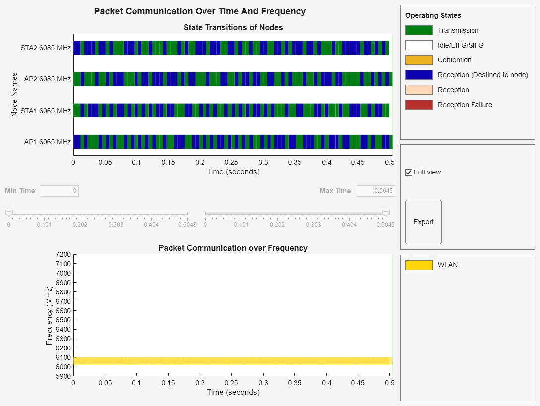
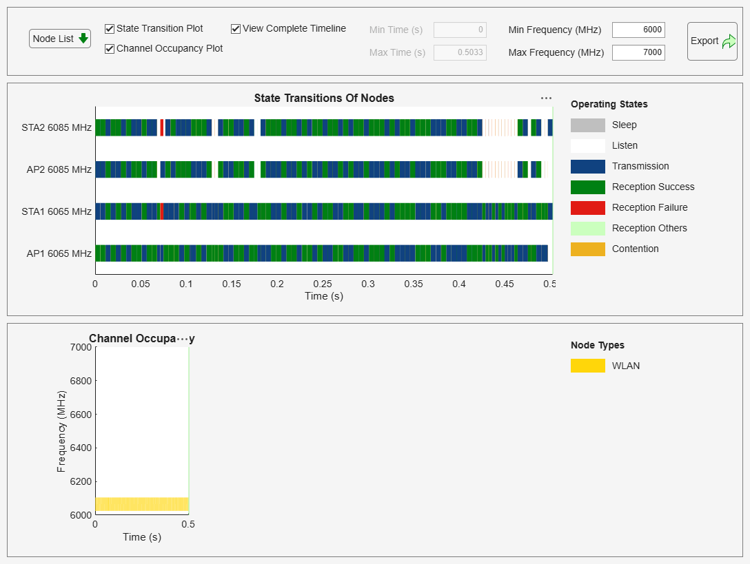
To visualize the packet communication, use the wirelessTrafficViewer object. The visualization shows these plots:
Packet communication over the time and frequency domains.
State transitions of each node over time.
Add the nodes to the wirelessTrafficViewer object by using the addNodes object function.
if enablePacketVisualization
    packetVisObj = wirelessTrafficViewer;
    addNodes(packetVisObj,nodes);
end
To view the node performance visualization, use the helperPerformanceViewer helper object.
perfViewerObj = helperPerformanceViewer(nodes,simulationTime);
Run the network simulation for the specified simulation time. The runtime visualization shows the packet communication in the time and frequency domains for the AP and the STAs. Note that the transmissions in BSS-1 and BSS-2 occur simultaneously, because the BSS-1 nodes primarily communicate in the primary 40 MHz channel and the BSS-2 nodes communicate in the secondary 40 MHz channel.
run(networkSimulator,simulationTime)
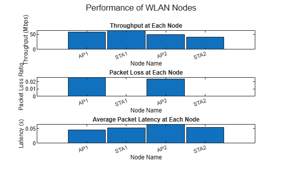
Use the plotNetworkStats object function to display these simulation plots.
MAC throughput (in Mbps) at each transmitter (APs and STAs).
MAC packet loss ratio (ratio of unsuccessful data transmissions to the total data transmissions) at each transmitter (APs and STAs).
Average application packet latency (in seconds) incurred at each receiver (APs and STAs). The average application packet latency shows the average latency that the STA incurs to receive the downlink traffic from the AP and the average latency that the AP incurs to receive uplink traffic from the STA.
if enableNodePerformancePlot
    plotNetworkStats(perfViewerObj)
end
Statistics
Retrieve the APP, MAC, and PHY statistics at each node by using the statistics object function of the wlanNode object. To retrieve the statistics for the links, in addition to the nodes, specify the "all" argument to the statistics object function. For more information on the statistics, see WLAN System-Level Simulation Statistics.
stats = statistics(nodes,"all");Compute the throughput (in Mbps) of BSS-1 and BSS-2. BSS-1 transmits the PPDU on the primary 40 MHz channel rather than the 80 MHz channel because the CCA state of the secondary channel is busy due to adjacent channel interference from BSS-2. Compare the throughputs of BSS-1 and BSS-2. Note that they are similar, which aligns with both BSSs using 40 MHz channels for transmission.
bss1throughput = sum(throughput(perfViewerObj,[apNode1.ID staNode1.ID]))
bss1throughput =
121.2960
bss2throughput = sum(throughput(perfViewerObj,[apNode2.ID staNode2.ID]))
bss2throughput =
91.8000
Appendix
This example uses these helpers:
hSLSTGaxMultiFrequencySystemChannel— Return a system channel objecthSLSTGaxAbstractSystemChannel— Return a channel object for an abstracted PHY layerhSLSTGaxSystemChannel— Return a channel object for full a PHY layerhSLSTGaxSystemChannelBase— Return the base channel objecthelperPerformanceViewer— Return a performance metrics viewer object
References
Park, Minyoung. "IEEE 802.11ac: Dynamic Bandwidth Channel Access." In 2011 IEEE International Conference on Communications (ICC), 1–5, 2011. https://doi.org/10.1109/icc.2011.5963089.
See Also
Objects
wlanNode|wlanMultilinkDeviceConfig|wlanLinkConfig|wirelessNetworkSimulator(Wireless Network Toolbox)