Resultados de
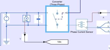
I was given a homework to make a Simscape IGBT rectifier, in which changing the delay angle leads to the conventional output. The input is 220 V 50 Hz supply, there are 2 gate pulses which I am providing using pulse generators (period 1/50 and pulse width 50%). The output, however is not correct. I am attaching the circuit diagram
and the incorrect output for a delay angle (α) 60 degrees. Can somebody point out the mistake? Thank you.
I have a datasheet of an induction motor (as figure below). I want to simulate it on matlab/simulink, but I don't know it's parameters (Lls, Llr, Lm, Rr, Rs).
I tried to search about open circuit test and blocked rotor test to determine these parameters, but some of information doesn't appear on datasheet and I don't have the real motor to test on it (datasheet is only think I have).
Could someone help me with this?
Attention all Controls Professors, Teaching Assistants, and Students!
The Virtual Hardware and Labs for Controls by Brian Hong is an absolute must-have from the MATLAB Central File Exchange. With the help of Simscape for physical modelling and simulation of mechatronic systems,
- students can use the interactive experiments to teach themselves some of the concepts of control theory in a learn by doing approach.
- professors and TA’s can use this to replace or augment actual lab work.
With tightening budgets and/or in person class restrictions this can help you transfer these vital skills to the students in a fun manner. Here is an overview of the available modules:
https://www.mathworks.com/matlabcentral/fileexchange/100064-virtual-hardware-and-labs-for-controls
If you have any questions feel free to leave a comment below and I’ll get back to you.
Prof. Ayse Tekes shares her story on teaching labs remotely with Simscape:
Hi All,
Quick question regarding deriving PM flux linkage [Wb] from a torque constant estimated from data on a PMLSM.
I have an estimated torque constant Kt [N/A], which is from experimental test data. I will now parameterising my Simscape PMLSM block from this torque constant.
The literature seems confusing, to derive PM flux linkage [Wb] from the experimental torque contant do i include the (3/2) constant. Some examples include the constant and some omit, which one of the following is preferred for deriving the PM flux linkage?
Thanks
Patrick
Hi All,
Using the PMLSM SimScape block for my FOC PMLSM model - PMLSM
In the example ee_pmlsm_drive.slx which i have based my FOC architedure on, have a few questions please.
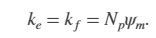
There is a gain block after the outer loop velocity controller (iq_Ref), which is the inverse of the Force constant (Kt) shown as (2/3*Np*PM) in the literature. This is also used in the PMSM FOC model, placed after the torque limiter Tq to iq_Ref. Why is this inverse Kt gain added to the idq_ref signal? Does this cancel Kt if its used in the Force Equation?

Previous help posts regarding the Force Constant (Kt), imply emitting the constant (3/2) in Kt. Also in the PMLSM help center document states Ke, Kt and Flux linkage are equal. Does this simplification apply to the translational machine counterpart SimScape block?
I have tried to look into the SimScape block code of the PMLSM to confirm, how do i look under the mask to check the Force equation for the PMLSM to confirm Kt and Ke used in this model?
Any help would be great as this is holding up Validation of my "small signal" linear PMLSM model against the SimScape PMLSM block model.
Thanks
Patrick
Hi All,
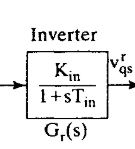
Looking for guidance on how to represent a PMSM 3-Phase Converter (DC bus to AC) as a simply 1st Order Transfer Function in my Simulink model.
Researching this, have found we can show the Power Converter as a simple gain and time delay such as G_inv(s) = K_Inv/(1 + T_inv s)

The gain requires V_cm, which is the control voltage, is this control voltage the "Forward Voltage, Vf" in Switching Devices tab in the block?
Is my assumption for the tf for the converter correct?
Thanks
Patrick
In this article, we discuss how educators can adopt simulation, alternative hardware, and other teaching resources to transition lab-based classes to distance learning: https://medium.com/mathworks/tips-for-moving-your-lab-based-classes-online-1cb53e90ee00.
Do you teach a lab-based class? Please share your thoughts, questions, experience, and feedback on these ideas here. I also welcome you to invite your colleagues to join the discussion here.
Hi, In my circuit, I have an element for which I don't have its equivalent circuit. What I have is a lookup table of its frequency response (magnitude and phase), which is complicated and cannot be represented by a lumped parameters equivalent circuit, and also some of its elements are frequency-dependent. Even if I do obtain somehow its transfer function Laplace representation (using e.g. "System identification" toolbox, and I want to add it to my circuit simulation (Simscape Electrical) as a block.
Does anyone have an idea how to do it? Thank you!