Resultados de
Hi everyone,
I am a third year BEng Energy Engineering student. I am looking at the design, modelling and peformance of an HVDC power converter for use in offshore wind for my final year dissertation. Power electronics is a new area for me and I am also new to simulink/ simscape elctrical.
Could anyone provide some useful examples of MMC (in particular rectifiers), or some advice for designing in simscape electrical. I am struggling with the design of PWM control especially. I aim to make a scaled down version of the MMC in Simulink but so far have had no luck. If anyone can help I would be really appreciative.
Thanks in advance.
Joe
Hi everyone, I'm trying to estimate the Frequency Response of a buck converter. I've found this article: https://it.mathworks.com/company/newsletters/articles/estimating-the-frequency-response-of-a-power-electronics-model.html I've adapted the procedure to a buck converter and followed the instructions but something went wrong. In the last step I've performed a time-domain verification in a Simulink® simulation with the switch-mode buck converter and a Transfer Function block implementing the parametric estimation and compare the response of both systems to the same small perturbation signal but the estimated model response doesn't match the switching model response. I don't know why I've got a diverging systems. I've tried to reduce the load and modify the duty cycle but nothing changed. How can I fix it?

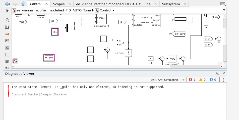
Dear power electronics control community,
Since I have not solved the problem and have not found an answer to why I receive such an output, I would be happy when you could help me out. The actual project is much more extensive but easy schematic of what I want to do is here:
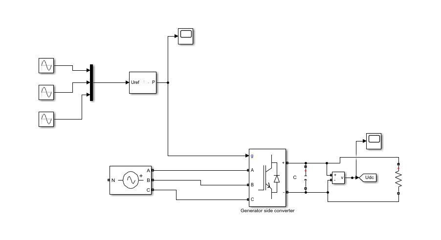
For that, I am using 2-level PWM generator: https://se.mathworks.com/help/physmod/sps/powersys/ref/pwmgenerator2level.html In the DC-link (DC voltage after the converter) the DC voltage output should be more-less constant (with a little noise) but right now it very far away from the desired output:
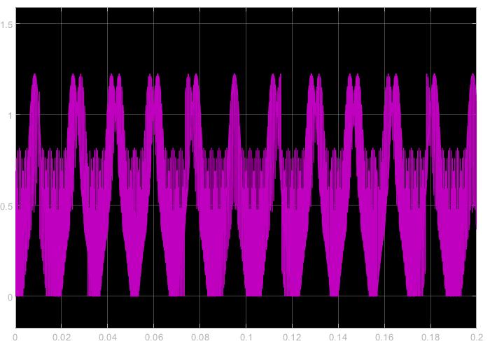
Does anyone have a idea what might cause this problem?
As usual, we start the autumn with a new release. R2019b is live! Check out what's new in Simscape™ Electrical™ . Load Flow Analysis, delta-wound PMSM and BLDC models, power dissipation for all machines, Japanese language localization support and many more new features. Please share your experience with the latest version of Simscape Electrical.