nrTDLChannel
Model TDL MIMO channel model
Description
The nrTDLChannel
System object™ models a tapped delay line (TDL) multi-input multi-output (MIMO) link-level
fading channel. The object implements the TDL models in TR 38.811 Section 6.9.2 [1] and the following aspects of
TR 38.901 [2]:
Section 7.7.2: TDL models
Section 7.7.3: Scaling of delays
Section 7.7.5.2 TDL extension: Applying a correlation matrix
Section 7.7.6: K-factor for LOS channel models
The object enables TDL channel filtering by default. When TDL channel filtering is enabled, you can send an input signal through the channel to obtain the channel-impaired signal. The default object also returns the path gains of the fading process and sample times of the channel snapshots.
The object also enables you to obtain the OFDM
channel response and timing offset when you set the ChannelResponseOutput property to 'ofdm-response'. In this
case, the object takes a carrier input, in addition to the input signal, and returns the OFDM
channel response and timing offset instead of the path gains and sample times, as shown in
this figure. (since R2024b)

To obtain channel characteristics without sending a signal through the
channel, set the ChannelFiltering property to false.
For an overview of how the object properties configure TDL channel filtering and channel coefficients generation, see Internal Architecture of TDL Channel Model.
To debug link-level simulations with unexpected
results, you can disable channel impairments by setting the DelayProfile property to
'None'. For more information on this channel behavior, see TDL Channel Model with Disabled Channel Impairments. (since R2026a)
To use the TDL MIMO channel model:
Create the
nrTDLChannelobject and set its properties.Call the object with arguments, as if it were a function.
To learn more about how System objects work, see What Are System Objects?
Creation
Description
tdl = nrTDLChannel
tdl = nrTDLChannel(PropertyName=Value)DelayProfile='TDL-D',DelaySpread=2e-6 creates
the channel object with the TDL-D delay profile and a 2-microseconds delay
spread.
Properties
Unless otherwise indicated, properties are nontunable, which means you cannot change their
values after calling the object. Objects lock when you call them, and the
release function unlocks them.
If a property is tunable, you can change its value at any time.
For more information on changing property values, see System Design in MATLAB Using System Objects.
Delay Profile Selection
The delay profile selection determines which delay profile configuration properties are applicable to the channel.
TDL delay profile, specified as one of these values.
'TDL-A','TDL-B','TDL-C','TDL-D', or'TDL-E'— These values correspond to the delay profiles defined in TR 38.901 Section 7.7.2, Tables 7.7.2-1 to 7.7.2-5.'TDLA30','TDLB100','TDLC300', or'TDLC60'— These values correspond to the simplified delay profiles defined in TS 38.101-4 Annex B.2.1 and TS 38.104 Annex G.2.1.'TDLD30','TDLA10', or'TDLD10'— These values correspond to the delay profiles defined in Release 17 of TS 38.101-4 Annexes B.2.1.1 and B.2.1.2. (since R2024a)'NTN-TDL-A','NTN-TDL-B','NTN-TDL-C', or'NTN-TDL-D'— These values correspond to the nonterrestrial network (NTN) delay profiles defined in TR 38.811 Section 6.9.2, Tables 6.9.2-1 to 6.9.2-4. (since R2024a)'NTN-TDLA100'and'NTN-TDLC5'— These values correspond to the simplified NTN delay profiles defined in TS 38.101-5 Annex B. (since R2024a)'Custom'— Configure the delay profile using thePathDelays,AveragePathGains,FadingDistribution, andKFactorFirstTapproperties.'None'— Disable channel impairments. Use this option when simulation results, such as error vector magnitude (EVM), throughput, or block error rate (BLER), deviate from expected values and you want to isolate the root cause. For an overview of how disabling channel impairments affects the TDL channel behavior, see TDL Channel Model with Disabled Channel Impairments. (since R2026a)
Data Types: char | string
Predefined Delay Profile
These properties configure channel parameters that are specific to predefined channel
profiles, that is, when you set DelayProfile to a value other than 'Custom'.
Desired root mean square (RMS) delay spread in seconds, specified as a numeric
scalar. For examples of desired RMS delay spreads,
DSdesired, see TR 38.901 Section
7.7.3 Tables 7.7.3-1 and 7.7.3-2.
Dependencies
To enable this property, set DelayProfile to 'TDL-A',
'TDL-B', 'TDL-C', 'TDL-D',
'TDL-E', 'NTN-TDL-A',
'NTN-TDL-B', 'NTN-TDL-C', or
'NTN-TDL-D'.
Data Types: double
K-factor scaling, specified as false or
true. When set to true, the KFactor
property specifies the desired K-factor, and the object applies K-factor scaling as
described in TR 38.901 Section 7.7.6.
Note
K-factor scaling modifies both the path delays and path powers.
Dependencies
To enable this property, set DelayProfile to 'TDL-D',
'TDL-E', 'NTN-TDL-C', or
'NTN-TDL-D'.
Data Types: double
Desired K-factor for scaling in dB, specified as a numeric scalar. For typical K-factor values, see TR 38.901 Section 7.7.6 and Table 7.5-6.
Note
K-factor scaling modifies both the path delays and path powers.
K-factorapplies to the overall delay profile. Specifically, the K-factor after the scaling isKmodelas described in TR 38.901 Section 7.7.6.Kmodelis the ratio of the power of the first path LOS to the total power of all the Rayleigh paths, including the Rayleigh part of the first path.
Dependencies
To enable this property, set DelayProfile to a
value other than 'None' and KFactorScaling to
true.
Data Types: double
Custom Delay Profile
These properties configure channel parameters that are specific to predefined channel
profiles, that is, when you set DelayProfile to 'Custom'.
Discrete path delays in seconds, specified as a numeric scalar or row vector.
AveragePathGains and PathDelays must have the same
size.
Dependencies
To enable this property, set DelayProfile to 'Custom'.
Data Types: double
Average path gains in dB, also referred to as cluster powers in TR 38.901,
specified as a numeric scalar or row vector. AveragePathGains and
PathDelays must have the
same size.
Dependencies
To enable this property, set DelayProfile to 'Custom'.
Data Types: double
Fading process statistical distribution, specified as
'Rayleigh' or 'Rician'.
Dependencies
To enable this property, set DelayProfile to 'Custom'.
Data Types: char | string
K-factor of first tap of delay profile in dB, specified as a numerical scalar. The default value corresponds to the K-factor of the first tap of TDL-D as defined in TR 38.901 Section 7.7.2, Table 7.7.2-4.
Dependencies
To enable this property, set DelayProfile to 'Custom' and FadingDistribution to 'Rician'.
Data Types: double
Antenna Array
These properties configure the MIMO correlation aspects of the channel.
Correlation between user equipment (UE) and base station (BS) antennas, specified as one of these values:
'Low'or'High'— Applies to both uplink and downlink.'Low'is equivalent to no correlation between antennas.'Medium'or'Medium-A'— For downlink, see TS 36.101 Annex B.2.3.2. For uplink, see TS 36.104 Annex B.5.2. TheTransmissionDirectionproperty controls the transmission direction.'UplinkMedium'— See TS 36.104, Annex B.5.2.'Custom'— TheReceiveCorrelationMatrixproperty specifies the correlation between UE antennas, and theTransmitCorrelationMatrixproperty specifies the correlation between BS antennas. See TR 38.901 Section 7.7.5.2.
For more details on correlation between UE and BS antennas, see TS 36.101 [3] and TS 36.104 [4].
Dependencies
To enable this property, set DelayProfile to a
value other than 'None'.
Data Types: char | string
Antenna polarization arrangement, specified as one of these values:
'Co-Polar'— The polarization arrangement of all antenna elements are identical.If the
MIMOCorrelationproperty is set to'Custom', use theReceiveCorrelationMatrixandTransmitCorrelationMatrixproperties to specify the receiver and transmit spatial correlation matrices, respectively.If
MIMOCorrelationis set to a predefined value, the object calculates the receiver and transmit spatial correlation matrices based onMIMOCorrelationand theNumReceiveAntennasandNumTransmitAntennasproperties, respectively.
'Cross-Polar'— The polarization arrangement is by pairs of antenna elements that form a cross.If the
MIMOCorrelationproperty is set to'Custom', use theTransmitPolarizationAngles,ReceivePolarizationAngles, andXPRproperties to define the polarization angles and power. Then use theReceiveCorrelationMatrixandTransmitCorrelationMatrixproperties to specify the receiver and transmit spatial correlation matrices, respectively.If
MIMOCorrelationis set to a predefined value, the object calculates the receiver and transmit spatial correlation matrices based onMIMOCorrelationand theNumReceiveAntennasandNumTransmitAntennasproperties, respectively.
'Custom'— Set theMIMOCorrelationproperty to'Custom', then use theSpatialCorrelationMatrixandNumTransmitAntennasproperties to define a custom configuration.
Dependencies
To enable this property, set DelayProfile to a
value other than 'None'.
Data Types: char | string
Transmission direction, specified as 'Downlink' or
'Uplink'.
Dependencies
To enable this property, set MIMOCorrelation to 'Low',
'Medium', 'Medium-A',
'UplinkMedium', or 'High'.
Note
This property describes the transmission direction corresponding to the
channel status in which the role of the transmit and receive antennas are not
swapped. If the antennas are swapped, the opposite transmission direction applies
to this property. To determine the current link direction of the channel, inspect
the TransmitAndReceiveSwapped property value.
Data Types: char | string
Number of transmit antennas, specified as a positive integer. You
can retrieve the number of antennas by using the info object
function.
Dependencies
To enable this property, set MIMOCorrelation to
'Low', 'Medium',
'Medium-A', 'UplinkMedium', or
'High', or set both MIMOCorrelation and
Polarization to
'Custom', or set DelayProfile to
'None'.
Data Types: double
Number of receive antennas, specified as a positive integer. You
can retrieve the number of antennas by using the info object
function.
Dependencies
To enable this property, set MIMOCorrelation to
'Low', 'Medium',
'Medium-A', 'UplinkMedium', or
'High' or set DelayProfile to
'None'.
Data Types: double
Spatial correlation of transmitter, specified as a 2-D matrix or 3-D array.
If the channel is frequency-flat (
PathDelaysis a scalar), specifyTransmitCorrelationMatrixas a 2-D Hermitian matrix of size NT-by-NT. NT is the number of transmit antennas. The main diagonal elements must be all ones, and the off-diagonal elements must have a magnitude smaller than or equal to one.If the channel is frequency-selective (
PathDelaysis a row vector of length NP), specifyTransmitCorrelationMatrixas one of these arrays:2-D Hermitian matrix of size NT-by-NT with element properties as previously described. Each path has the same transmit correlation matrix.
3-D array of size NT-by-NT-by-NP, where each submatrix of size NT-by-NT is a Hermitian matrix with element properties as previously described. Each path has its own transmit correlation matrix.
Dependencies
To enable this property, set DelayProfile to a
value other than 'None', then set MIMOCorrelation to
'Custom' and Polarization to either
'Co-Polar' or 'Cross-Polar'.
Data Types: double
Complex Number Support: Yes
Spatial correlation of receiver, specified as a 2-D matrix or 3-D array.
If the channel is frequency-flat (
PathDelaysis a scalar), specifyReceiveCorrelationMatrixas a 2-D Hermitian matrix of size NR-by-NR. NR is the number of receive antennas. The main diagonal elements must be all ones, and the off-diagonal elements must have a magnitude smaller than or equal to one.If the channel is frequency-selective (
PathDelaysis a row vector of length NP), specifyReceiveCorrelationMatrixas one of these arrays:2-D Hermitian matrix of size NR-by-NR with element properties as previously described. Each path has the same receive correlation matrix.
3-D array of size NR-by-NR-by-NP, where each submatrix of size NR-by-NR is a Hermitian matrix with element properties as previously described. Each path has its own receive correlation matrix.
Dependencies
To enable this property, set DelayProfile to a
value other than 'None', then set MIMOCorrelation to
'Custom' and Polarization to either
'Co-Polar' or 'Cross-Polar'.
Data Types: double
Complex Number Support: Yes
Transmit polarization slant angles in degrees, specified as a row vector.
Dependencies
To enable this property, set DelayProfile to a
value other than 'None', then set MIMOCorrelation to
'Custom' and Polarization to
'Cross-Polar'.
Data Types: double
Receive polarization slant angles in degrees, specified as a row vector.
Dependencies
To enable this property, set DelayProfile to a
value other than 'None', then set MIMOCorrelation to
'Custom' and Polarization to
'Cross-Polar'.
Data Types: double
Cross-polarization power ratio in dB, specified as a numeric scalar or a row vector. This property corresponds to the ratio between the vertical-to-vertical (PVV) and vertical-to-horizontal (PVH) polarizations defined for the clustered delay line (CDL) models in TR 38.901 Section 7.7.1.
If the channel is frequency-flat (
PathDelaysis a scalar), specifyXPRas a scalar.If the channel is frequency-selective (
PathDelaysis a row vector of length NP), specifyXPRas one of these values:Scalar — Each path has the same cross-polarization power ratio.
Row vector of size 1-by-NP — Each path has its own cross-polarization power ratio.
The default value corresponds to the cluster-wise cross-polarization power ratio of CDL-A as defined in TR 38.901 Section 7.7.1, Table 7.7.1-1.
Dependencies
To enable this property, set DelayProfile to a
value other than 'None', then set MIMOCorrelation to
'Custom' and Polarization to
'Cross-Polar'.
Data Types: double
Combined correlation for the channel, specified as 2-D matrix or 3-D array. The matrix determines the product of the number of transmit antennas (NT) and the number of receive antennas (NR).
If the channel is frequency-flat (
PathDelaysis a scalar), specifySpatialCorrelationMatrixas a 2-D Hermitian matrix of size (NT ⨉ NR)-by-(NT ⨉ NR).The magnitude of any off-diagonal element must be no larger than the geometric mean of the two corresponding diagonal elements.If the channel is frequency-selective (
PathDelaysis a row vector of length NP), specifySpatialCorrelationMatrixas one of these arrays:2-D Hermitian matrix of size (NT ⨉ NR)-by-(NT ⨉ NR) with off-diagonal element properties as previously described. Each path has the same spatial correlation matrix.
3-D array of size (NT ⨉ NR)-by-(NT ⨉ NR)-by-NP array — where each matrix of size (NT ⨉ NR)-by-(NT ⨉ NR) is a Hermitian matrix with off-diagonal element properties as previously described. Each path has its own spatial correlation matrix.
Dependencies
To enable this property, set DelayProfile to a
value other than 'None', then set MIMOCorrelation to
'Custom' and Polarization to
'Custom'.
Data Types: double
Mobility
These properties configure how the transmitter or receiver move.
Maximum Doppler shift in Hz, specified as a nonnegative numeric scalar. This
property applies to all channel paths. When both the maximum Doppler shift and
satellite Doppler shift are set to 0, the channel remains static for the entire input.
To generate a new channel realization, either reset the object by calling the
reset function or set the satellite
Doppler shift to a nonzero value in case of NTN profiles.
Dependencies
To enable this property, set DelayProfile to a
value other than 'None'.
Data Types: double
Since R2024a
Satellite Doppler shift in Hz, specified as a numeric scalar. Satellite Doppler
shift is calculated using the satellite altitude, elevation angle, carrier frequency,
and satellite velocity. The default value of
SatelliteDopplerShift corresponds to the Doppler shift due to a
satellite having an elevation angle of 90 degrees. When both the maximum Doppler shift
and satellite Doppler shift are set to 0, the channel remains static for the entire
input. To generate a new channel realization, either reset the object by calling the
reset function or set the satellite
Doppler shift to a nonzero value in case of NTN profiles.
Tunable: Yes
Dependencies
To enable this property, set DelayProfile to 'NTN-TDL-A',
'NTN-TDL-B', 'NTN-TDL-C',
'NTN-TDL-D', 'NTN-TDLA100', or
'NTN-TDLC5'.
Data Types: double
Channel Control
These properties configure implementation-specific parameters of the channel that are not defined by TR 38.901. For example, you can enable or disable channel filtering, set the data type and the number of samples of the filtered signal, and set control parameters for the path gain generation.
Sample rate of the input signal in Hz, specified as a positive numeric scalar.
Dependencies
To enable this property, set DelayProfile to a
value other than 'None'.
Data Types: double
Since R2024b
Sample rate for path gain generation, specified as one of these values:
'signal'— The channel uses the sample rate specified by theSampleRateproperty for the path gain generation.'auto'— Use this option to enable the channel to automatically reduce the number of path gain samples based on the maximum Doppler shift value. The channel usesmin(as the sample rate for the path gain generation. If the maximum Doppler shift is set toMaximumDopplerShift⨯2⨯64,SampleRate)0, the channel generates one path gain per antenna per path.
Dependencies
To enable this property, set DelayProfile to a
value other than 'None'.
Data Types: char | string
Normalized channel fading process, specified as true or
false. When this property is set to true, the
amplitude of the channel fading process is normalized by the average path gains (also
referred to as cluster powers in TR 38.901). When this property is set to
false, the channel fading process is not normalized. The
DelayProfile property
determines the average path gains,
based on TR 38.901
Section 7.7.2, Tables 7.7.2-1 to 7.7.2-5. When you set DelayProfile to 'Custom', you can specify the average
path gains with the AveragePathGains
property.
Dependencies
To enable this property, set DelayProfile to a
value other than 'None'.
Data Types: logical
Time offset of fading process in seconds, specified as a numeric scalar.
Dependencies
To enable this property, set DelayProfile to a
value other than 'None'.
Data Types: double
Number of modeling sinusoids, specified as a positive integer. These sinusoids model the fading process.
Dependencies
To enable this property, set DelayProfile to a
value other than 'None'.
Data Types: double
Source of the random number stream to initialize the sinusoid phases using uniformly distributed random numbers, specified as one of these values.
'mt19937ar with seed'— The object uses the mt19937ar algorithm for the random number generation. Calling theresetfunction resets the filters and reinitializes the random number stream to the value of theSeedproperty. Specifying this value results in repeatable channel fading.'Global stream'— The object uses the current global random number stream for the random number generation. Calling theresetfunction resets only the filters.
Dependencies
To enable this property, set DelayProfile to a
value other than 'None'.
Initial seed of mt19937ar random number stream, specified as a nonnegative numeric scalar.
Dependencies
To enable this property, set DelayProfile to a
value other than 'None', then set RandomStream to
'mt19937ar with seed'. When calling the reset function, the seed reinitializes the mt19937ar random number
stream.
Data Types: double
Normalize channel outputs, specified as true or
false. When this property is set to true, the
channel outputs are normalized by the number of receive antenna elements.
Note
When you call the swapTransmitAndReceive function to reverse the role of the transmit
and receive antennas within the channel, the function also swaps the NumTransmitAntennas and NumReceiveAntennas properties. Hence the normalization is always by
the number of receive antenna elements, specified by the NumReceiveAntennas property.
Data Types: logical
Since R2024b
Channel response output, specified as one of these options:
'path-gains'— The object returns the path gains and sample times, as shown in this figure. When channel filtering is enabled, the object also returns the filtered output signal. Alternatively, to configure the channel to return only the path gains and sample times, set theChannelFilteringproperty tofalseto disable channel filtering.
'ofdm-response'— The object returns the OFDM channel response and timing offset when you call the object with a carrier input, as shown in this figure. When channel filtering is enabled, the object also returns the filtered output signal. Alternatively, to configure the channel to return only the OFDM channel response and timing offset, set theChannelFilteringproperty tofalseto disable channel filtering.
Data Types: string | char
Fading channel filtering, specified as one of these options:
true— Enable channel filtering. The object takes an input signal to filter through the channel.false— Disable channel filtering. The object takes no input signal and returns only the OFDM channel response and timing offset (since R2024b) or the path gains and sample times, depending on theChannelResponseOutputproperty.When you disable channel filtering, these conditions apply:
The
NumTimeSamplesproperty controls the duration of the fading process realization at a sample rate given by theSampleRateproperty.The
OutputDataTypeproperty specifies the data type of the generated channel response output (OFDM channel response or path gains).
For an overview of how this property affects the internal architecture of the channel, see Internal Architecture of TDL Channel Model.
For a use case of disabling channel filtering, see the Calculate OFDM Channel Response of TDL Channel example.
Data Types: logical
Number of time samples, specified as a positive integer. When channel filtering is disabled, you can use this property to set the duration of the fading process realization.
When you call the object with the carrier
input, carrier, set the NumTimeSamples
property to a value that is at least the number of samples in a slot. You can
calculate the number of samples in a slot from the output structure of
nrOFDMInfo(carrier). (since R2024b)
Tunable: Yes
Dependencies
To enable this property, set DelayProfile to a
value other than 'None' and set ChannelFiltering to
false.
Data Types: double
Data type of the generated channel response output, specified as
'double' or 'single'. When channel filtering
is disabled, use this property to specify the data type of the OFDM channel response (since R2024b) or path gains, depending on the ChannelResponseOutput property.
Dependencies
To enable this property, set ChannelFiltering to false.
Data Types: double
Read-Only Properties
This property is read-only.
Reversed channel link direction, returned as one of these values.
false— The role of the transmit and receive antennas within the channel model corresponds to the original channel link direction. Calling theswapTransmitAndReceivefunction on thenrTDLChannelobject reverses the link direction of the channel and toggles this property value fromfalsetotrue.true— The role of the transmit and receive antennas within the channel model are swapped. Calling theswapTransmitAndReceivefunction on thenrTDLChannelobject restores the original link direction of the channel and toggles this property value fromtruetofalse.
Data Types: logical
Usage
Syntax
Description
Channel Filtering
OFDM Channel Response and Timing Offset
Since R2024b
To use these syntaxes, set the ChannelResponseOutput property to 'ofdm-response'.
[
applies OFDM demodulation to the channel impulse response based on the specified
carrier, signalOut,ofdmResponse] = tdl(signalIn,carrier)carrier, and returns the OFDM channel response, in
addition to the channel-impaired signal. This output shows how the channel affects each
resource element of an OFDM signal.
[
also returns the timing offset of the strongest path in the channel impulse response.
The channel impulse response is averaged across all channel snapshots and summed across
all transmit and receive antennas.signalOut,ofdmResponse,timingOffset] = tdl(signalIn,carrier)
[
returns only the OFDM channel response and timing offset without filtering an input
signal. The ofdmResponse,timingOffset] = tdl(carrier)tdl object and the carrier input act
as a source for the calculation of the OFDM channel response and timing offset. To use
this syntax, you must also set the ChannelFiltering property to false.
Path Gains and Sample Times
To use these syntaxes, set the ChannelResponseOutput property to
'path-gains' (since R2024b).
[
also returns the sample times of the channel snapshots of signalOut,pathGains,sampleTimes] = tdl(signalIn)pathGains
(first-dimension elements).
[
returns only the path gains and sample times without filtering an input signal. The
pathGains,sampleTimes] = tdl()tdl object acts as a source for the calculation of the path gains
and sample times. To use this syntax, you must also set the ChannelFiltering property to false.
Input Arguments
Output Arguments
Object Functions
To use an object function, specify the
System object as the first input argument. For
example, to release system resources of a System object named obj, use
this syntax:
release(obj)
Examples
Create a default carrier configuration object.
carrier = nrCarrierConfig;
Create a TDL channel object with the TDL-B delay profile.
channel = nrTDLChannel;
channel.DelayProfile = "TDL-B";
channel.MaximumDopplerShift = 200;
Set the sample rate of the channel to match the sample rate of the carrier.
ofdmInfo = nrOFDMInfo(carrier);
channel.SampleRate = ofdmInfo.SampleRate;
Specify the OFDM channel response as the channel output.
channel.ChannelResponseOutput = "ofdm-response";Disable channel filtering.
channel.ChannelFiltering = false;
Set the number of time samples to generate a single-slot OFDM response.
channel.NumTimeSamples = sum(ofdmInfo.SymbolLengths(1:carrier.SymbolsPerSlot));
Call the TDL channel object by specifying the carrier input. The object returns the OFDM channel response and timing offset of the TDL channel.
[ofdmResponse,timingOffset] = channel(carrier);
Display the OFDM channel response.
mesh(abs(ofdmResponse(:,:,1,1)));
title('OFDM Channel Response of TDL Channel');
xlabel('OFDM Symbol'); ylabel("Subcarrier"); zlabel("Magnitude");

Display the waveform spectrum received through a tapped delay line (TDL) multi-input/multi-output (MIMO) channel model from TR 38.901 Section 7.7.2 using an nrTDLChannel System object.
Define the channel configuration structure using an nrTDLChannel System object. Use delay profile TDL-C from TR 38.901 Section 7.7.2, a delay spread of 300 ns, and UE velocity of 30 km/h:
v = 30.0;                    % UE velocity in km/h
fc = 4e9;                    % carrier frequency in Hz
c = physconst('lightspeed'); % speed of light in m/s
fd = (v*1000/3600)/c*fc;     % UE max Doppler frequency in Hz

tdl = nrTDLChannel;
tdl.DelayProfile = 'TDL-C';
tdl.DelaySpread = 300e-9;
tdl.MaximumDopplerShift = fd;
Create a random waveform of 1 subframe duration with 1 antenna.
SR = 30.72e6;
T = SR * 1e-3;
tdl.SampleRate = SR;
tdlinfo = info(tdl);
Nt = tdlinfo.NumTransmitAntennas;

txWaveform = complex(randn(T,Nt),randn(T,Nt));
Transmit the input waveform through the channel.
rxWaveform = tdl(txWaveform);
Plot the received waveform spectrum.
analyzer = spectrumAnalyzer('SampleRate',tdl.SampleRate);
analyzer.Title = ['Received Signal Spectrum ' tdl.DelayProfile];
analyzer(rxWaveform);
![]()
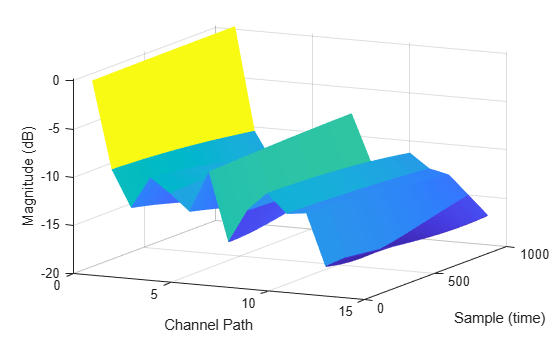
Plot the path gains of a tapped delay line (TDL) single-input/single-output (SISO) channel using an nrTDLChannel object.
Configure a channel with delay profile TDL-E from TR 38.901 Section 7.7.2. Set the maximum Doppler shift to 70 Hz and enable path gain output.
tdl = nrTDLChannel;
tdl.SampleRate = 500e3;
tdl.MaximumDopplerShift = 70;
tdl.DelayProfile = 'TDL-E';
Configure the transmit and receive antenna arrays for SISO operation.
tdl.NumTransmitAntennas = 1;
tdl.NumReceiveAntennas = 1;
Create a dummy input signal. The length of the input determines the time samples of the generated path gain.
in = zeros(1000,tdl.NumTransmitAntennas);
To generate the path gains, call the channel on the input. Plot the results.
[~, pathGains] = tdl(in);
mesh(10*log10(abs(pathGains)));
view(26,17); xlabel('Channel Path');
ylabel('Sample (time)'); zlabel('Magnitude (dB)');
Display the waveform spectrum received through a tapped delay line (TDL) channel model using delay profile TDL-D from TR 38.901 Section 7.7.2.
Configure 4-by-2, high-correlation, cross-polar antennas as specified in TS 36.101 Annex B.2.3A.3.
tdl = nrTDLChannel;
tdl.NumTransmitAntennas = 4;
tdl.DelayProfile = 'TDL-D';
tdl.DelaySpread = 10e-9;
tdl.KFactorScaling = true;
tdl.KFactor = 7.0;
tdl.MIMOCorrelation = 'High';
tdl.Polarization = 'Cross-Polar';
Create a random waveform of 1 subframe duration with 4 antennas.
SR = 1.92e6;
T = SR * 1e-3;
tdl.SampleRate = SR;
tdlinfo = info(tdl);
Nt = tdlinfo.NumTransmitAntennas;

txWaveform = complex(randn(T,Nt),randn(T,Nt));
Transmit the input waveform through the channel.
rxWaveform = tdl(txWaveform);
Plot the received waveform spectrum.
analyzer = spectrumAnalyzer('SampleRate',tdl.SampleRate);
analyzer.Title = ['Received Signal Spectrum ' tdl.DelayProfile];
analyzer(rxWaveform);
![]()
Transmit waveform through a tapped delay line (TDL) channel model from TR 38.901 Section 7.7.2 with customized delay profile.
Define the channel configuration structure using an nrTDLChannel System object. Customize the delay profile with two taps.
First tap: Rician with average power 0 dB, K-factor 10 dB, and zero delay.
Second tap: Rayleigh with average power 5 dB, and 45 ns path delay using TDL-D.
tdl = nrTDLChannel;
tdl.NumTransmitAntennas = 1;
tdl.DelayProfile = 'Custom';
tdl.FadingDistribution = 'Rician';
tdl.KFactorFirstTap = 10.0;
tdl.PathDelays = [0.0 45e-9];
tdl.AveragePathGains = [0.0 -5.0];
Create a random waveform of 1 subframe duration with 1 antenna.
SR = 30.72e6;
T = SR * 1e-3;
tdl.SampleRate = SR;
tdlinfo = info(tdl);
Nt = tdlinfo.NumTransmitAntennas;

txWaveform = complex(randn(T,Nt),randn(T,Nt));
Transmit the input waveform through the channel.
rxWaveform = tdl(txWaveform);
Display the waveform spectrum received through an NTN-TDL channel model from TR 38.811 Section 6.9.2 with NTN-TDL-A delay profile.
Configure an NTN channel with NTN-TDL-A delay profile for a satellite moving at an altitude of 600 km with a speed of 7562.2 m/s and having an elevation angle of 50 degrees with the user equipment (UE).
ntnChan = nrTDLChannel;
ntnChan.DelayProfile = 'NTN-TDL-A';
ntnChan.DelaySpread = 100e-9;
Calculate the maximum Doppler shift due to the UE and satellite Doppler shift.
r = physconst('earthradius');                  % Earth radius in m
c = physconst('lightspeed');                   % Speed of light in m/s
fc = 2e9;                                      % Carrier frequency in Hz
theta = 50;                                    % Elevation angle in degrees
h = 600e3;                                     % Satellite altitude in m
vSat = 7562.2;                                 % Satellite speed in m/s
vUE = 3*1000/3600;                             % UE speed in m/s
fdMaxUE = (vUE*1000/3600)/c*fc;                % UE maximum Doppler shift in Hz
fdSat = (vSat*fc/c)*(r*cosd(theta)/(r+h));     % Satellite Doppler shift in Hz
ntnChan.SatelliteDopplerShift = fdSat;
ntnChan.MaximumDopplerShift = fdMaxUE;
Create a random waveform of 1 subframe duration with 1 antenna.
SR = 30.72e6;
T = SR*1e-3;
ntnChan.SampleRate = SR;
ntnChanInfo = info(ntnChan);
Nt = ntnChanInfo.NumTransmitAntennas;
txWaveform = randn(T,Nt,'like',1i);
Transmit the input waveform through the channel.
rxWaveform = ntnChan(txWaveform);
Plot the received waveform spectrum.
analyzer = spectrumAnalyzer('SampleRate',ntnChan.SampleRate);
analyzer.Title = ['Received Signal Spectrum ' ntnChan.DelayProfile];
analyzer(rxWaveform);
![]()
Algorithms
The object properties configure the TDL channel filtering and channel coefficients generation.
To enable or disable TDL channel filtering, use the ChannelFiltering property.
TDL Channel Filtering Enabled — When you set
ChannelFilteringtotrue, the object accepts an input signal and returns the channel-impaired signal. Depending on theChannelResponseOutputproperty, the object returns also the:OFDM channel response and timing offset (when
ChannelResponseOutput='ofdm-response'). (since R2024b)Path gains and sample times (when
ChannelResponseOutput='path-gains').
This figure shows the internal architecture of the TDL channel model when channel filtering is enabled and the object returns the OFDM channel response and timing offset. (since R2024b)

TDL Channel Filtering Disabled — When you set
ChannelFilteringtofalse, the object does not accept an input signal. However, depending on theChannelResponseOutputproperty, the object returns the:OFDM channel response and timing offset (when
ChannelResponseOutput='ofdm-response'). (since R2024b)Path gains and sample times (when
ChannelResponseOutput='path-gains').
Use the
OutputDataTypeandNumTimeSamplesproperties to set the channel response output data type and the duration of the fading process realization, respectively.This figure shows the internal architecture of the TDL channel model when channel filtering is disabled and the object returns only the OFDM channel response and timing offset. (since R2024b)

To configure TR 38.901-specific parameters:
Set the delay profile,
DelayProfile, then configure delay-profile-specific parameters. Depending on the delay profile, use the properties listed in the Predefined Delay Profile or Custom Delay Profile sections.Configure the MIMO correlation aspects of the channel by using the properties listed in the Antenna Array section.
Configure the UE mobility by using the properties listed in the Mobility section.
To configure non-TR 38.901-specific implementation details of the coefficients generation, use the properties listed in the Channel Control section.
References
[1] 3GPP TR 38.811. “Study on New Radio (NR) to support non-terrestrial networks.” 3rd Generation Partnership Project; Technical Specification Group Radio Access Network.
[2] 3GPP TR 38.901. “Study on channel model for frequencies from 0.5 to 100 GHz.” 3rd Generation Partnership Project; Technical Specification Group Radio Access Network.
[3] 3GPP TS 36.101. “Evolved Universal Terrestrial Radio Access (E-UTRA); User Equipment (UE) radio transmission and reception.” 3rd Generation Partnership Project; Technical Specification Group Radio Access Network.
[4] 3GPP TS 36.104. “Evolved Universal Terrestrial Radio Access (E-UTRA); Base Station (BS) radio transmission and reception.” 3rd Generation Partnership Project; Technical Specification Group Radio Access Network.
[5] 3GPP TS 38.101-5. “NR; User Equipment (UE) radio transmission and reception; Part 5: Satellite access Radio Frequency (RF) and performance requirements.” 3rd Generation Partnership Project; Technical Specification Group Radio Access Network.
Extended Capabilities
Version History
Introduced in R2018bSee Also
Functions
Objects
Apps
Topics
- TDD Reciprocity-Based PDSCH MU-MIMO Using SRS
- Model NR NTN Channel (Satellite Communications Toolbox)
- NR NTN PDSCH Throughput