patchMicrostrip
Create regular or AI-based microstrip patch antenna
Description
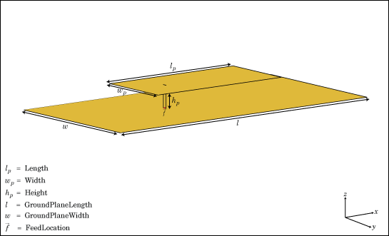
The default patchMicrostrip object is a microstrip patch antenna
resonating around 1.75 GHz. The default patch is centered at the origin. The feed point is along
the length of the antenna.
You can perform full-wave EM solver based analysis on the regular
patchMicrostrip antenna or you can create a patchMicrostrip type
AIAntenna and explore the design space to tune the antenna for your application
using AI-based analysis.
Creation
Description
pm = patchMicrostrip
pm = patchMicrostrip(PropertyName=Value)PropertyName is
the property name and Value is the corresponding value. You can specify
several name-value arguments in any order as
PropertyName1=Value1,...,PropertyNameN=ValueN. Properties that you do not
specify, retain their default values.
You can also create a
patchMicrostripantenna resonating at a desired frequency using thedesignfunction.You can also create a
patchMicrostripantenna from a microstrip patch typeAIAntennaobject using theexportAntennafunction.A
patchMicrostriptypeAIAntennahas some common tunable properties with a regularpatchMicrostripantenna for AI-based analysis. Other properties of the regularpatchMicrostripantenna are retained as read-only in itsAIAntennaequivalent. To find the upper and lower bounds of the tunable properties, usetunableRangesfunction.
Properties
Object Functions
axialRatio | Calculate and plot axial ratio of antenna or array |
bandwidth | Calculate and plot absolute bandwidth of antenna or array |
beamwidth | Beamwidth of antenna |
charge | Charge distribution on antenna or array surface |
current | Current distribution on antenna or array surface |
design | Create antenna, array, or AI-based antenna resonating at specified frequency |
efficiency | Calculate and plot radiation efficiency of antenna or array |
EHfields | Electric and magnetic fields of antennas or embedded electric and magnetic fields of antenna element in arrays |
feedCurrent | Calculate current at feed for antenna or array |
impedance | Calculate and plot input impedance of antenna or scan impedance of array |
info | Display information about antenna, array, or platform |
memoryEstimate | Estimate memory required to solve antenna or array mesh |
mesh | Generate and view mesh for antennas, arrays, and custom shapes |
meshconfig | Change meshing mode of antenna, array, custom antenna, custom array, or custom geometry |
msiwrite | Write antenna or array analysis data to MSI planet file |
optimize | Optimize antenna and array catalog elements using SADEA or TR-SADEA algorithm |
pattern | Plot radiation pattern of antenna, array, or embedded element of array |
patternAzimuth | Azimuth plane radiation pattern of antenna or array |
patternElevation | Elevation plane radiation pattern of antenna or array |
peakRadiation | Calculate and mark maximum radiation points of antenna or array on radiation pattern |
rcs | Calculate and plot monostatic and bistatic radar cross section (RCS) of platform, antenna, or array |
resonantFrequency | Calculate and plot resonant frequency of antenna |
returnLoss | Calculate and plot return loss of antenna or scan return loss of array |
show | Display antenna, array, AI-based antenna, platform, or shape |
sparameters | Calculate S-parameters for antenna or array |
stlwrite | Write mesh information to STL file |
vswr | Calculate and plot voltage standing wave ratio (VSWR) of antenna or array element |
Examples
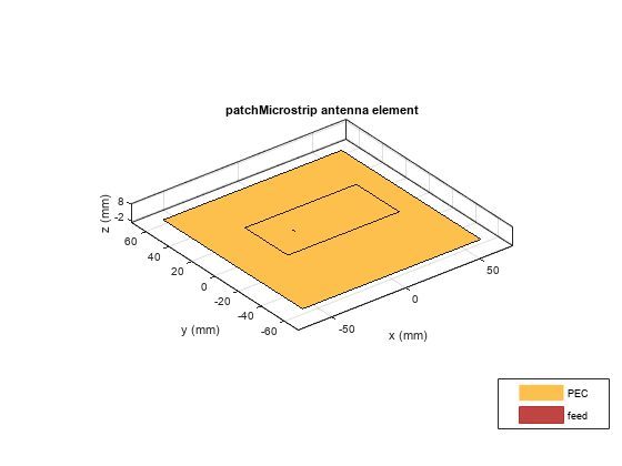
Create and view a microstrip patch with specified parameters.
pm = patchMicrostrip(Length=75e-3, Width=37e-3, ...
         GroundPlaneLength=120e-3, GroundPlaneWidth=120e-3)
pm =
patchMicrostrip with properties:
Length: 0.0750
Width: 0.0370
Height: 0.0060
Substrate: [1×1 dielectric]
GroundPlaneLength: 0.1200
GroundPlaneWidth: 0.1200
PatchCenterOffset: [0 0]
FeedOffset: [-0.0187 0]
Conductor: [1×1 metal]
Tilt: 0
TiltAxis: [1 0 0]
Load: [1×1 lumpedElement]
show (pm)
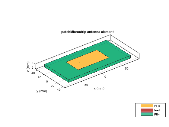
Create a microstrip patch antenna using FR4 dielectric substrate.
d = dielectric("FR4"); pm = patchMicrostrip(Length=75e-3, Width=37e-3, ... GroundPlaneLength=120e-3, GroundPlaneWidth=120e-3, ... Substrate=d)
pm =
  patchMicrostrip with properties:

               Length: 0.0750
                Width: 0.0370
               Height: 0.0060
            Substrate: [1×1 dielectric]
    GroundPlaneLength: 0.1200
     GroundPlaneWidth: 0.1200
    PatchCenterOffset: [0 0]
           FeedOffset: [-0.0187 0]
            Conductor: [1×1 metal]
                 Tilt: 0
             TiltAxis: [1 0 0]
                 Load: [1×1 lumpedElement]
show(pm)

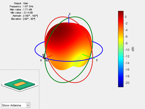
Plot the radiation pattern of the antenna at a frequency of 1.67 GHz.
figure
pattern(pm,1.67e9)
Create a microstrip patch antenna using FR4 dielectric substrate.
d = dielectric("FR4");
pm = patchMicrostrip(Substrate=d)
pm =
patchMicrostrip with properties:
Length: 0.0750
Width: 0.0375
Height: 0.0060
Substrate: [1×1 dielectric]
GroundPlaneLength: 0.1500
GroundPlaneWidth: 0.0750
PatchCenterOffset: [0 0]
FeedOffset: [-0.0187 0]
Conductor: [1×1 metal]
Tilt: 0
TiltAxis: [1 0 0]
Load: [1×1 lumpedElement]
show(pm)
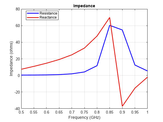
Calculate and plot the impedance of the antenna over the specified frequency range.
impedance(pm,linspace(0.5e9,1e9,11));
Design a prototype microstrip patch antenna that resonates at a frequency of 1 GHz.
p = design(patchMicrostrip,1e9)
p =
  patchMicrostrip with properties:

               Length: 0.1439
                Width: 0.1874
               Height: 0.0030
            Substrate: [1×1 dielectric]
    GroundPlaneLength: 0.2998
     GroundPlaneWidth: 0.2998
    PatchCenterOffset: [0 0]
           FeedOffset: [0.0303 0]
            Conductor: [1×1 metal]
                 Tilt: 0
             TiltAxis: [1 0 0]
                 Load: [1×1 lumpedElement]
show(p)

Calculate the impedance of the above antenna at the same frequency.
Z = impedance(p,1e9)
Z =
47.8027 - 7.5678i
This example shows how to create an AI-based microstrip patch antenna operating at 1.67 GHz, and calculate its bandwidth and resonant frequency.
Use the design function with the ForAI argument set to true to create an AI-based microstrip patch antenna operating at 1.67 GHz. To use the ForAI argument in the design function you need a license to the Statistics and Machine Learning Toolbox™.
pAI = design(patchMicrostrip,1.67e9,ForAI=true)
pAI =
  AIAntenna with properties:

   Antenna Info
               AntennaType: 'patchMicrostrip'
    InitialDesignFrequency: 1.6700e+09

   Tunable Parameters
                    Length: 0.0862
                     Width: 0.1122
                    Height: 0.0018

Show read-only properties
Explore the design space by changing its length and width with values within the tunable range of these properties. You can get the tunable range of a property by using tunableRanges function on the AI-based antenna object.
pAI.Length = 0.0855;
pAI.Width = 0.113;
Calculate the absolute bandwidth of the antenna and its lower and upper bounds.
[absBW,fL,fU,matchingStatus] = bandwidth(pAI)
absBW =
2.3422e+07
fL =
1.6679e+09
fU =
1.6913e+09
matchingStatus = categorical
     Matched
Calculate the resonant frequency of the antenna.
fR = resonantFrequency(pAI)
fR =
1.7016e+09
Convert the AI-based microstrip patch antenna to a regular microstrip patch antenna.
pm = exportAntenna(pAI)
pm =
  patchMicrostrip with properties:

               Length: 0.0855
                Width: 0.1130
               Height: 0.0018
            Substrate: [1×1 dielectric]
    GroundPlaneLength: 0.1795
     GroundPlaneWidth: 0.1795
    PatchCenterOffset: [0 0]
           FeedOffset: [0.0181 0]
            Conductor: [1×1 metal]
                 Tilt: 0
             TiltAxis: [1 0 0]
                 Load: [1×1 lumpedElement]
References
[1] Balanis, Constantine A. Antenna Theory: Analysis and Design. Fourth edition. Hoboken, New Jersey: Wiley, 2016.
Version History
Introduced in R2015aSee Also
Objects
Functions
Topics
- Miniaturize Rectangular Microstrip Patch Antenna Using Genetic Algorithm Optimization
- Artificial Intelligence (AI) for Rapid Analysis and Design of Patch Antenna
- ISM Band Microstrip Patch Antennas and Mutually Coupled Patches
- Design and Simulate Monopulse Tracking System (RF Blockset)
- Model Infinite Ground Plane for Unbalanced Antennas
- Rotate Antennas and Arrays
- Infinite Ground Plane