PCBReader
Import and update Gerber files
Description
Use the PCBReader object to create a printed circuit board
(PCB) reader to import Gerber files and to facilitate the creation of an antenna model. A
Gerber file is a set of manufacturing files used to describe a PCB antenna. A Gerber file uses
an ASCII vector format to describe 2-D binary images.
Creation
You can create a PCBReader object using the following methods:
gerberRead— Create aPCBReaderobject with the specified Gerber and drill files.The
PCBReaderfunction described here.
Description
B = PCBReader( creates a
S)PCBReader object that imports multilayer PCB antenna design files
described in the stackUp
object.
Note
To translate the center of an imported symmetrical or asymmetrical polygon to
[0,0]use the following MATLAB® functions,boundingboxandcentroid. See examples.
The
PCBReaderobject reads RS-274X Gerber files. It does not support RS-274D Gerber files.
B = PCBReader( sets
properties
using one or more name-value arguments. PropertyName=Value)PropertyName is the property
name and Value is the corresponding value. You can specify several
name-value arguments in any order as PropertyName1=Value1,
..., PropertyNameN=ValueN. Properties that you
do not specify retain their default values.
For example, B = PCBReader(StackUp=S,Drillfile='ant.txt') imports
the layer and drill files into the PCBReader.
Input Arguments
Properties
Object Functions
shapes | Extract and modify metal layers from PCBReader
object |
Examples
Create a default PCB stackup definition object.
S = stackUp;
Set the thickness of the dielectric Air in layer 1 and layer 5 of the stackUp object to 0.1 mm.
S.Layer1.Thickness = 0.1e-3;
S.Layer5.Thickness = 0.1e-3;
Import a top layer Gerber file to layer 2.
S.Layer2 = "antenna_design_file.gtl";Import a bottom layer Gerber file to layer 4.
S.Layer4 = "antenna_design_file.gbl";Create a PCBReader object, B, using the stackUp object, S.
B = PCBReader(StackUp=S);
Visualize the individual layers.
sh = shapes(B);
figure
show(sh(1))
title("Top Layer")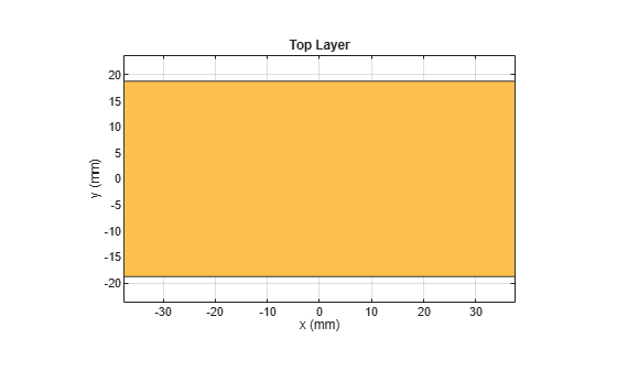
figure
show(sh(2))
title("Bottom Layer")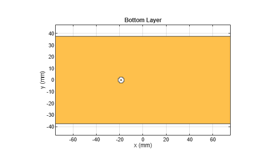
Create a default PCB stackup definition object.
s = stackUp;
Import a top layer Gerber file to layer 2.
s.Layer2 = "patchMicrostripCircular_design_file.gtl";Import a bottom layer Gerber file to layer 4.
s.Layer4 = "patchMicrostripCircular_design_file.gbl";Create a PCBReader object using the stackUp object.
p = PCBReader(StackUp=s);
To update the Gerber file, convert the PCBReader object to a pcbStack object.
p3 = pcbStack(p);
View the pcbStack object.
figure
show(p3)
title("Circular Patch Antenna")
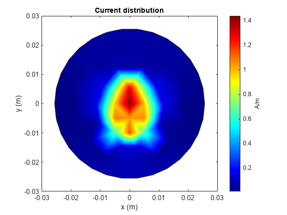
Update the feed locations and feed diameter.
p3.FeedLocations = [5e-3 0 2 4];
p3.FeedDiameter = 0.005;
View the updated pcbStack object.
figure
show(p3)
title("Circular Patch Antenna with Reduced Feed Diameter")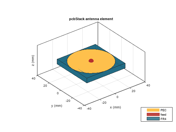
Plot the current distribution on the antenna at 2.4 GHz.
figure
current(p3,2.4e9)
Create a PCBReader object.
B = PCBReader;
Import a two-layer design.
st = B.StackUp;
st.Layer2 = "UWBVivaldi.gtl";
st.Layer4 = "UWBVivaldi.gbl";
B.StackUp = st;
Extract shapes from the metal layers.
S = shapes(B);
View the top-layer Gerber file.
figure
show(S(1))

View the bottom-layer Gerber file.
figure
show(S(2))

This example will show how to translate the symmetrical polygon imported from the Gerber file to the respective co-ordinates.
Create a PCB stackup and import rectangular patch on it.
S = stackUp;
S.Layer2 = "PatchRectangular.gtl";
S.Layer3 = dielectric("Teflon");
Use a PCB Reader to read the polygon shape from the stackup.
p1 = PCBReader(StackUp=S);
figure
show(p1.shapes)

Translate the shape with center (0,0) using the centriod function from MATLAB.
s = p1.shapes
s =
  Polygon with properties:

        Name: 'mypolygon'
    Vertices: [4×3 double]
polygon = s;
[x,y] = centroid(polygon);
translate(polygon,[-x, -y, 0]);

This example shows how to translate the asymmetrical polygon imported from the Gerber file to the respective co-ordinates.
Create a PCB stackup and import rectangular patch on it.
S = stackUp;
S.Layer2 = "RightAngleBend.gtl";
S.Layer3 = dielectric("Teflon");
Use a PCB Reader to read the polygon shape from the stackup.
p1 = PCBReader(StackUp=S);
figure
show(p1.shapes)

Translate the shape's bottom left corner to (0,0). Use the boundingbox function from MATLAB to convert the shape to polyshape and find the upper and lower bounds of the shape.
s = p1.shapes
s =
  Polygon with properties:

        Name: 'mypolygon'
    Vertices: [6×3 double]
ver = s.Vertices(:,1:2);
polygon = polyshape(ver);
[xlim, ylim] = boundingbox(polygon);
translate(s,[-xlim(1), -ylim(1), 0]);

Version History
Introduced in R2020b
See Also
PCBWriter | PCBServices | PCBConnectors | pcbStack | stackUp | gerberRead