Configure AUTOSAR Sender-Receiver Communication
In AUTOSAR port-based sender-receiver (S-R) communication, AUTOSAR software components read and write data to other components or services. To implement S-R communication, AUTOSAR software components define:
An AUTOSAR sender-receiver interface with data elements.
AUTOSAR provide and require ports that send and receive data.
In Simulink®, you can:
Create AUTOSAR S-R interfaces and ports by using the AUTOSAR Dictionary, or if using a Simulink data dictionary, using the Architectural Data Editor.
Model AUTOSAR provide and require ports by using Simulink root-level outports and inports.
Map the outports and inports to AUTOSAR provide and require ports by using the Code Mappings editor.
Note
If you are using a Simulink data dictionary to store interfaces, you must configure these interfaces using either the Architectural Data Editor or the relevant programmatic interfaces,
Simulink.dictionary.ArchitecturalData.
For queued sender-receiver communication, see Configure AUTOSAR Queued Sender-Receiver Communication.
For an example modeling sender-receiver communication using Simulink bus ports, see Configure AUTOSAR Ports By Using Simulink Bus Ports.
For an example modeling ErrorStatus ports and End-to-End
protection, see Configure AUTOSAR Sender-Receiver Interface Ports for End-to-End Protection.
Configure AUTOSAR Sender-Receiver Interface
This procedure outlines the general workflow for modeling AUTOSAR sender and
receiver components in Simulink. This example assumes that a Simulink data dictionary is not used to store interfaces. If you are using a
Simulink data dictionary to store interfaces, you must configure these
interfaces using either the Architectural
Data Editor or the relevant programmatic interfaces, Simulink.dictionary.ArchitecturalData.
To create an S-R interface and ports in Simulink:
Open the AUTOSAR Dictionary and select S-R Interfaces. Click the Add button
 to create a new AUTOSAR S-R data
interface. Specify its name and the number of associated S-R data
elements.
to create a new AUTOSAR S-R data
interface. Specify its name and the number of associated S-R data
elements.Select and expand the new S-R interface. Select DataElements, and modify the AUTOSAR data element attributes.

In the AUTOSAR Dictionary, expand the AtomicComponents node and select an AUTOSAR component. Expand the component.
Select and use the ReceiverPorts, SenderPorts, and SenderReceiverPorts views to add AUTOSAR S-R ports that you want to associate with the new S-R interface. For each new S-R port, select the S-R interface you created.
Optionally, examine the communication attributes for each S-R port and modify where required. For more information, see Configure AUTOSAR Sender-Receiver Port Communication Specification Attributes.

Open the Code Mappings editor. Select and use the Inports and Outports tabs to map Simulink inports and outports to AUTOSAR S-R ports. For each inport or outport, select an AUTOSAR port, data element, and data access mode.

Configure AUTOSAR Provide-Require Port
AUTOSAR Release 4.1 introduced the AUTOSAR provide-require port
(PRPort). Modeling an AUTOSAR PRPort
involves using a Simulink inport and outport pair with matching data type, dimension, and signal
type. You can associate a PRPort with a sender-receiver (S-R)
interface or a nonvolatile (NV) data interface.
To configure an AUTOSAR PRPort for S-R communication in
Simulink:
Open a model that is configured for AUTOSAR, and in which a runnable has an inport and an outport suitable for pairing into an AUTOSAR
PRPort. In this example, theRPort_DE1inport andPPort_DE1outport both use data typeint8, port dimension 1, and signal typereal.Open the AUTOSAR Dictionary and navigate to the SenderReceiverPorts view. (To configure a
PRPortfor NV communication, use the NvSenderReceiverPorts view instead.)To add a sender-receiver port, click the Add button
. In the Add Ports dialog box, specify
Name as PRPortand select an Interface from the list of available S-R interfaces. Click Add.
Open the Code Mappings editor and select the Inports tab. To map a Simulink inport to the AUTOSAR sender-receiver port you created, select the inport, set Port to the value
PRPort, and set Element to a data element that the inport and outport will share.
Select the Outports tab. To map a Simulink outport to the AUTOSAR sender-receiver port you created, select the outport, set Port to the value
PRPort, and set Element to the same data element selected in the previous step.
Click the Validate button
 to validate the updated AUTOSAR component
configuration. If errors are reported, address them and then retry
validation. A common error flagged by validation is mismatched properties
between the inport and outport that are mapped to the AUTOSAR
to validate the updated AUTOSAR component
configuration. If errors are reported, address them and then retry
validation. A common error flagged by validation is mismatched properties
between the inport and outport that are mapped to the AUTOSAR
PRPort.
Alternatively , you can programmatically add and map a PRPort
port using AUTOSAR property and map functions. The following example adds an AUTOSAR
PRPort (sender-receiver port) and then maps it to a
Simulink inport and outport pair.
hModel = 'my_autosar_expfcns';
open_system(hModel)
arProps = autosar.api.getAUTOSARProperties(hModel);
swcPath = find(arProps,[],'AtomicComponent')
swcPath =
'ASWCadd(arProps,'ASWC','SenderReceiverPorts','PRPort','Interface','Interface1') prportPath = find(arProps,[],'DataSenderReceiverPort')
prportPath =
    'ASWC/PRPort'
slMap = autosar.api.getSimulinkMapping(hModel); mapInport(slMap,'RPort_DE1','PRPort','DE1','ImplicitReceive') mapOutport(slMap,'PPort_DE1','PRPort','DE1','ImplicitSend') [arPortName,arDataElementName,arDataAccessMode] = getOutport(slMap,'PPort_DE1')
arPortName =
PRPort

arDataElementName =
DE1

arDataAccessMode =
ImplicitSend
Configure AUTOSAR Receiver Port for IsUpdated Service
AUTOSAR defines quality-of-service attributes, such as
ErrorStatus and IsUpdated, for
sender-receiver interfaces. The IsUpdated attribute allows an
AUTOSAR explicit receiver to detect whether a receiver port data element has
received data since the last read occurred. When data is idle, the receiver can save
computational resources.
For the sender, the AUTOSAR Runtime Environment (RTE) sets the status of an update
flag, indicating whether the data element has been written. The receiver calls the
Rte_IsUpdated_
API, which reads the update flag and returns a value indicating whether the data
element has been updated since the last read.Port_Element
In Simulink, you can:
Import an AUTOSAR receiver port for which
IsUpdatedservice is configured.Configure an AUTOSAR receiver port for
IsUpdatedservice.Generate C and ARXML code for an AUTOSAR receiver port for which
IsUpdatedservice is configured.
To model IsUpdated service in Simulink, you pair an inport that is configured for
ExplicitReceive data access with a new inport configured for
IsUpdated data access. To configure an AUTOSAR receiver port
for IsUpdated service:
Open a model for which an AUTOSAR sender-receiver interface is configured.
Identify the inport that corresponds to the AUTOSAR receiver port for which
IsUpdatedservice is required. Create a second inport, set its data type toboolean, and connect it to the same block. For example:
Open the Code Mappings editor. Select the Inports tab. In the inports view, configure the mapping properties for both inports.
If the data inport is not already configured, set DataAccessMode to
ExplicitReceive. Select Port and Element values that map the inport to the AUTOSAR receiver port and data element for whichIsUpdatedservice is required.For the quality-of-service inport, set DataAccessMode to
IsUpdated. Select Port and Element values that exactly match the data inport.

To validate the AUTOSAR component configuration, click the Validate button
.Build the model and inspect the generated code. The generated C code contains an
Rte_IsUpdatedAPI call.tmpIsUpdated = Rte_IsUpdated_Input_DE1(); … if (tmpIsUpdated) { … (void)Rte_Read_Input_DE1(&tmpRead); … }The exported ARXML code contains the ENABLE-UPDATE setting
truefor the AUTOSAR receiver port.<R-PORT-PROTOTYPE UUID="..."> <SHORT-NAME>Input</SHORT-NAME> <REQUIRED-COM-SPECS> <NONQUEUED-RECEIVER-COM-SPEC> <DATA-ELEMENT-REF DEST="VARIABLE-DATA-PROTOTYPE">/pkg/if/Input/DE1 </DATA-ELEMENT-REF> … <ENABLE-UPDATE>true</ENABLE-UPDATE> … </NONQUEUED-RECEIVER-COM-SPEC> </REQUIRED-COM-SPECS> … </R-PORT-PROTOTYPE>
Be aware that using both ErrorStatus and
IsUpdated quality-of-service attributes on a receiver can
result in less efficient code. In such a case, the generated
Rte_Read call is outside of the conditional
IsUpdated statement, but use of the data read from the
Rte_Read call is within the conditionally executed code.
rtb_TmpSignalConversionAtErrorS = Rte_Read_Input_DE1
  (&rtb_TmpSignalConversionAtIn1Out);
…
if (Rte_IsUpdated_Input_DE1()) {

  model_ARID_DEF.Gain = rtb_TmpSignalConversionAtIn1Out << 14;
  model_ARID_DEF.ErrorStatus = rtb_TmpSignalConversionAtErrorS;
}
Configure AUTOSAR Sender-Receiver Data Invalidation
The AUTOSAR standard defines an invalidation mechanism for AUTOSAR data elements used in sender-receiver (S-R) communication. A sender component can notify a downstream receiver component that data in a sender port is invalid. Each S-R data element can have an invalidation policy. In Simulink, you can:
Import AUTOSAR sender-receiver data elements for which an invalidation policy is configured.
Use a Signal Invalidation block to model sender-receiver data invalidation for simulation and code generation. Using block parameters, you can specify a signal invalidation policy and an initial value for an S-R data element.
Generate C code and ARXML descriptions for AUTOSAR sender-receiver data elements for which an invalidation policy is configured.
For each S-R data element, you can set the Signal Invalidation
block parameter Signal invalidation policy to
Keep, Replace, or
DontInvalidate. If an input data value is invalid
(invalidation control flag is true), the resulting action is
determined by the value of Signal invalidation policy:
Keep- Replace the input data value with the last valid signal value.Replace- Replace the input data value with an Initial value parameter.DontInvalidate- Do not replace the input data value.

To configure an invalidation policy for an AUTOSAR S-R data element in Simulink:
Open a model for which an AUTOSAR sender-receiver interface is configured. For example, suppose that:
A Simulink outport named
Outis mapped to AUTOSAR sender portPPortand data elementOutElem. In the AUTOSAR Dictionary, AUTOSAR sender portPPortselects S-R interfaceOut, which contains the data elementOutElem.A Simulink inport named
In1is mapped to AUTOSAR receiver portRPort1and data elementInElem1. In the AUTOSAR Dictionary, AUTOSAR receiver portRPort1selects S-R interfaceIn1, which contains the data elementInElem1. In the Code Mappings editor, Inports tab, here is the mapping for inportIn1.


Add a Signal Invalidation block to the model.
The block must be connected directly to a root outport block. Connect the block to root outport
Out.Connect the first block input, a data value, to the data path from root inport
In1.For the second block input, an invalidation control flag, add a root inport named
In2to the model. Set its data type to scalarboolean. Map the new inport to a second AUTOSAR receiver port. If a second AUTOSAR receiver port does not exist, use the AUTOSAR Dictionary to create the AUTOSAR port, S-R interface, and data element.In this example, Simulink inport
In2is mapped to AUTOSAR receiver portRPort2and data elementInElem2. In the AUTOSAR Dictionary, AUTOSAR receiver portRPort2selects S-R interfaceIn2, which contains the data elementInElem2.Connect the second block input to root inport
In2.


View the Signal Invalidation block parameters dialog box. Examine the Signal invalidation policy and Initial value attributes. For more information, see the Signal Invalidation block reference page.

Open the Code Mappings editor and select the Outports tab. For the root outport
Out, verify that the AUTOSAR data access mode is set toExplicitSendorEndToEndWrite.
To validate the AUTOSAR component configuration, open the Code Mappings editor and click the Validate button
.Build the model and inspect the generated code. When the signal is valid, the generated C code calls
Rte_Write_. When the signal is invalid, the C code callsPort_ElementRte_Invalidate_.Port_Element/* SignalInvalidation: '<Root>/Signal Invalidation' incorporates: * Inport: '<Root>/In2' */ if (!Rte_IRead_Runnable_Step_RPort2_InElem2()) { /* Outport: '<Root>/Out' */ (void) Rte_Write_PPort_OutElem(mSignalInvalidation_B.Gain); } else { Rte_Invalidate_PPort_OutElem(); }The exported ARXML code contains the invalidation setting for the data element.
<INVALIDATION-POLICY>
    <DATA-ELEMENT-REF DEST="VARIABLE-DATA-PROTOTYPE">/pkg/if/Out/OutElem</DATA-ELEMENT-REF>
    <HANDLE-INVALID>KEEP</HANDLE-INVALID>
</INVALIDATION-POLICY>
Configure AUTOSAR Receiver Port for DataReceiveErrorEvent
In AUTOSAR sender-receiver communication between software components, the Runtime
Environment (RTE) raises a DataReceiveErrorEvent when the
communication layer reports an error in data reception by the receiver component.
For example. the event can indicate that the sender component failed to reply within
an AliveTimeout limit, or that the sender component sent invalid
data.
Embedded Coder® supports creating DataReceiveErrorEvents in
AUTOSAR receiver components. In Simulink, you can:
Import an AUTOSAR
DataReceiveErrorEventdefinition.Define a
DataReceiveErrorEvent.Export ARXML and generate code for AUTOSAR receiver ports for which a
DataReceiveErrorEventis configured.
You should configure a DataReceiveErrorEvent for an
AUTOSAR receiver port that uses ImplicitReceive,
ExplicitReceive, or
EndToEndRead data access mode.
To configure an AUTOSAR receiver port for a
DataReceiveErrorEvent:
Open a model for which the receiver side of an AUTOSAR sender-receiver interface is configured.
Open the Code Mappings editor. Select the Inports tab. Select the data inport that is mapped to the AUTOSAR receiver port for which you want to configure a
DataReceiveErrorEvent. Set its AUTOSAR data access mode toImplicitReceive,ExplicitReceive, orEndToEndRead. Here are two examples, without and with a coupledErrorStatusport.

Open the AUTOSAR Dictionary. Expand the AtomicComponents node. Expand the receiver component and select Runnables.
In the runnables view, create a runnable to handle
DataReceiveErrorEvents.Click the Add button
to add a runnable entry.Select the new runnable entry to configure its name and other properties.
Go to the Events pane, and configure a
DataReceiveErrorEventfor the runnable. Click Add Event, select typeDataReceiveErrorEvent, and enter an event name.Under Event Properties, select the trigger for the event. The selected trigger value indicates the AUTOSAR receiver port and the data element for which the runnable is handling
DataReceiveErrorEvents.
Alternatively, you can programmatically create a
DataReceiveErrorEvent.arProps = autosar.api.getAUTOSARProperties(mdlname); add(arProps,ibQName,'Events','DRE_Evt',... 'Category','DataReceiveErrorEvent','Trigger','rPort.DE1',... 'StartOnEvent',runnableQName);
Build the model and inspect the generated code. The exported ARXML code defines the error-handling runnable and its triggering event.
<EVENTS>
    <DATA-RECEIVE-ERROR-EVENT UUID="...">
        <SHORT-NAME>DRE_Evt</SHORT-NAME>
        <START-ON-EVENT-REF DEST="RUNNABLE-ENTITY">
          /Root/mDemoModel_swc/ReceivingASWC/IB/Run_ErrorHandling</START-ON-EVENT-REF>
        <DATA-IREF>
            <CONTEXT-R-PORT-REF DEST="R-PORT-PROTOTYPE">
              /Root/mDemoModel_swc/ReceivingASWC/rPort</CONTEXT-R-PORT-REF>
            <TARGET-DATA-ELEMENT-REF DEST="VARIABLE-DATA-PROTOTYPE">
              /Root/Interfaces/In/DE</TARGET-DATA-ELEMENT-REF>
        </DATA-IREF>
    </DATA-RECEIVE-ERROR-EVENT>
</EVENTS>
...
<RUNNABLES>
    ...
    <RUNNABLE-ENTITY UUID="...">
        <SHORT-NAME>Run_ErrorHandling</SHORT-NAME>
        <MINIMUM-START-INTERVAL>0</MINIMUM-START-INTERVAL>
        <CAN-BE-INVOKED-CONCURRENTLY>false</CAN-BE-INVOKED-CONCURRENTLY>
        ...
        <SYMBOL>Run_ErrorHandling</SYMBOL>
    </RUNNABLE-ENTITY>
</RUNNABLES>
Configure AUTOSAR Sender Port for DataSendCompletedEvent
In AUTOSAR sender-receiver communication between software components, the Runtime
Environment (RTE) can trigger runnables when data transmission is completed by using
DataSendCompletedEvent events.
In Simulink, you can:
Import an AUTOSAR
DataSendCompletedEventdefinition.Define a
DataSendCompletedEventevent associated with an AUTOSAR sender port to trigger an AUTOSAR runnable.Export ARXML and generate code for AUTOSAR sender ports for which a
DataSendCompletedEventevent is configured.
You can configure a DataSendCompletedEvent event for an AUTOSAR
sender port that uses one of these explicit data access modes:
ExplicitSend or QueuedExplicitSend.
To configure an AUTOSAR sender port for a
DataSendCompletedEvent event:
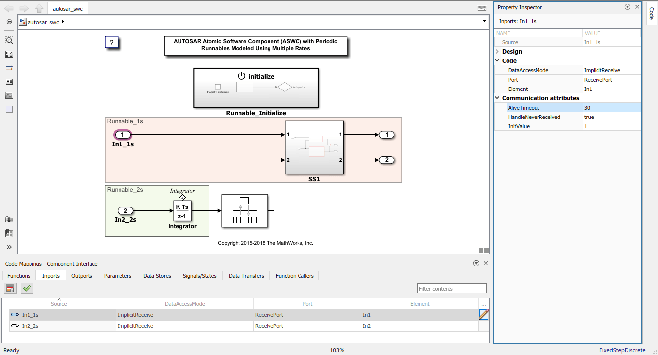
Open a model for which the sender side of an AUTOSAR sender-receiver interface is configured. The steps that follow use the example model
autosar_swc_expfcns.Open the Code Mappings editor. Select the Outports tab. Select the outport that is mapped to the AUTOSAR sender port for which you want to configure a
DataSendCompletedEventevent. Set its AUTOSAR data access mode to eitherExplicitSendorQueuedExplicitSend.
Open the AUTOSAR Dictionary. Expand the AtomicComponents node. Expand ASWC and select Runnables. In the right pane, select existing runnable
Runnable1.In the Events pane delete the previously configured
TimingEventEvent_t_1tic_A.Add a
DataSendCompletedEventevent by clicking the Add Event button. Select event typeDataSendCompletedEvent, and enter an event name.Under Event Properties, select the trigger for the event. The selected trigger value indicates that the AUTOSAR sender port and the data element for which the runnable is handling a
DataSendCompletedEventevent.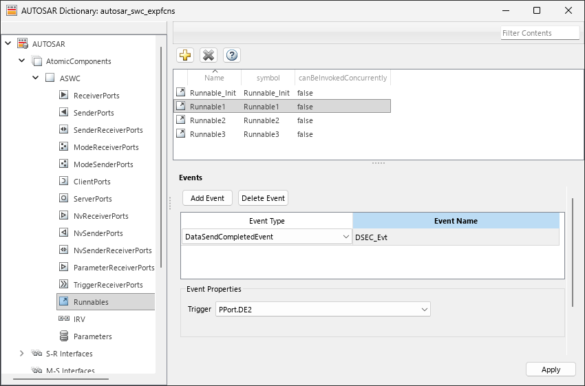
Return to the model and change the Sample Time of Inport block
Runnable1to-1.Enter subsystem
Runnable1_subsystemand on the block parameters for the Trigger block change Sample time type fromperiodictotriggered. Now that the runnable no longer handles aTimingEventevent it cannot be triggered periodically.
Alternatively, you can programmatically create and configure a
DataSendCompletedEvent
event.
openExample("autosar_swc_expfcns");
slMap = autosar.api.getSimulinkMapping("autosar_swc_expfcns");
mapOutport(slMap,"PPort_DE2","PPort","DE2","ExplicitSend");
arProps = autosar.api.getAUTOSARProperties("autosar_swc_expfcns");
add(arProps,"/pkg/swc/ASWC/IB", ...
    "Events","DSCE_Evt", ...
    "Category","DataSendCompletedEvent", ...
    "Trigger","PPort.DE2", ...
    "StartOnEvent","ASWC/IB/Runnable1");
When you export and inspect ARXML descriptions for the model. The exported ARXML defines the runnable and its triggering event.
...
<EVENTS>
    <DATA-SEND-COMPLETED-EVENT UUID="...">
        <SHORT-NAME>DSCE_Evt</SHORT-NAME>
        <START-ON-EVENT-REF DEST="RUNNABLE-ENTITY">/pkg/swc/ASWC/IB/Runnable1</START-ON-EVENT-REF>
        <EVENT-SOURCE-REF DEST="VARIABLE-ACCESS">/pkg/swc/ASWC/IB/Runnable3/OUT_PPort_DE2</EVENT-SOURCE-REF>
    </DATA-SEND-COMPLETED-EVENT>
</EVENTS>
...
Configure AUTOSAR Sender-Receiver Port Communication Specification Attributes
In AUTOSAR software components, a sender or receiver port can specify communication specification (ComSpec) attributes. ComSpecs describe additional communication requirements for port data. This example shows how to map Simulink ports to AUTOSAR receiver ports in Simulink®, and then specify ComSpec attributes both visually in the software, as well as programmatically.
To model AUTOSAR sender and receiver ComSpecs in Simulink, you can:
Import sender and receiver ComSpecs from ARXML files.
Create sender and receiver ComSpecs in Simulink.
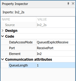
For non-queued receiver ports, modify ComSpec attributes
AliveTimeout,HandleNeverReceived, andInitValue.For queued receiver ports, modify ComSpec attribute
QueueLength.Export ComSpec attributes to ARXML files.
Graphically Configure AUTOSAR Sender-Receiver Port ComSpecs
For example, if you create an AUTOSAR receiver port in Simulink®, you use the Code Mappings editor to map a Simulink® inport to the AUTOSAR receiver port and a sender-receiver data element. You can then select the port and specify its ComSpec attributes.
For queued receiver ports the only ComSpec attribute is QueueLength.
If you import or create an AUTOSAR receiver port, you can use the AUTOSAR Dictionary to view and edit the ComSpec attributes of the mapped sender-receiver data elements of the AUTOSAR port.
Programmatically Configure AUTOSAR Sender-Receiver Port Communication Specification Attributes
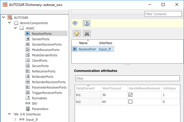
Open example model autosar_swc and create the associated autosar.api.getAUTOSARProperties object.
hModel = "autosar_swc";
open_system(hModel);
arProps = autosar.api.getAUTOSARProperties(hModel);
By using the arProps property object, find the paths of the DataReceiverPort, sender receiver interface Input_If, sender receiver data element In1, and the temporary information paths to access the communication specifications.
portPath = find(arProps,[],"DataReceiverPort","PathType","FullyQualified");
ifPath = find(arProps,[],"SenderReceiverInterface","Name","Input_If","PathType","FullyQualified");
dataElementPath = find(arProps,ifPath{1},"FlowData","Name","In1","PathType","FullyQualified");
infoPath = find(arProps,portPath{1},"PortInfo",...
    "PathType","FullyQualified","DataElements",dataElementPath{1});
comSpecPath = find(arProps,infoPath{1},"PortComSpec","PathType","FullyQualified");
For the non-queued port in example model autosar_swc set the communication specification attribute values.
Starting in R2025a, valid values for InitValue include heterogeneous values like arrays, matrices, and structures for ports that are typed by busses. When you assign a structure for the InitValue of a port typed by a bus, the values of the structure must be consistent with the values of the bus typed to the port.
set(arProps,comSpecPath{1},"AliveTimeout",30,"HandleNeverReceived",true,"InitValue",1);
get(arProps,comSpecPath{1},"AliveTimeout")
ans = 30
get(arProps,comSpecPath{1},"HandleNeverReceived")ans = logical
1
get(arProps,comSpecPath{1},"InitValue")ans = 1
For queued receiver ports you can only set QueueLength.
set(arProps,comSpecPath,"QueueLength",10);
When you generate code for an AUTOSAR model that specifies ComSpec attributes, the exported ARXML port descriptions include the ComSpec attribute values.
<PORTS>
    <R-PORT-PROTOTYPE UUID="...">
        <SHORT-NAME>ReceivePort</SHORT-NAME>
        <REQUIRED-COM-SPECS>
            <NONQUEUED-RECEIVER-COM-SPEC>
                <DATA-ELEMENT-REF DEST="VARIABLE-DATA-PROTOTYPE">
                  /Company/Powertrain/Interfaces/Input_If/In1
                </DATA-ELEMENT-REF>
...
                <ALIVE-TIMEOUT>30</ALIVE-TIMEOUT>
                <HANDLE-NEVER-RECEIVED>true</HANDLE-NEVER-RECEIVED>
...
                <INIT-VALUE>
                    <CONSTANT-REFERENCE>
                        <SHORT-LABEL>DefaultInitValue_Double_1</SHORT-LABEL>
                        <CONSTANT-REF DEST="CONSTANT-SPECIFICATION">
                          /Company/Powertrain/Constants/DefaultInitValue_Double_1
                        </CONSTANT-REF>
                    </CONSTANT-REFERENCE>
                </INIT-VALUE>
            </NONQUEUED-RECEIVER-COM-SPEC>
        </REQUIRED-COM-SPECS>
    </R-PORT-PROTOTYPE>
</PORTS>
...
<CONSTANT-SPECIFICATION UUID="...">
    <SHORT-NAME>DefaultInitValue_Double_1</SHORT-NAME>
    <VALUE-SPEC>
      <NUMERICAL-VALUE-SPECIFICATION>
          <SHORT-LABEL>DefaultInitValue_Double_1</SHORT-LABEL>
          <VALUE>1</VALUE>
      </NUMERICAL-VALUE-SPECIFICATION>
  </VALUE-SPEC>
</CONSTANT-SPECIFICATION>