Kasami Sequence Generator
Generate Kasami sequence from set of Kasami sequences
Libraries:
Communications Toolbox /
Comm Sources /
Sequence Generators
Description
The Kasami Sequence Generator block generates a sequence from a set of Kasami sequences. The Kasami sequences are a set of sequences that have good cross-correlation properties. For more information, see Kasami Sequences.
This block can output sequences that vary in length during simulation. For more information about variable-size signals, see Variable-Size Signal Basics (Simulink).
These icons show the block with oSiz, Ref
and Rst ports enabled.
![]()
![]()
Examples
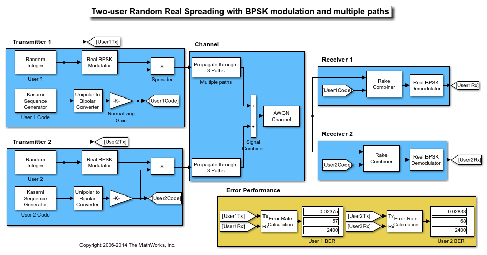
Kasami Spreading for Multiuser System in Multipath Channel
This model simulates Kasami sequence spreading for two users in a multipath transmission environment. This is similar to a mobile channel environment where the signals are received over multiple paths. Each path can have different amplitudes and delays. The receiver combines the independent paths coherently using diversity reception to realize gains from the multipath transmissions received. The modeled system does not simulate fading effects and the receiver gets perfect knowledge of the number of paths and their respective delays.
Ports
Input
Output
Parameters
Block Characteristics
Data Types |
|
Multidimensional Signals |
|
Variable-Size Signals |
|
More About
Before you can reset the generator sequence, you must select the
Reset on nonzero input parameter to enable the
Rst input port. Suppose that the Kasami Sequence Generator block outputs
[1 0 0 1 1 0 1 1] when no reset exists. This table shows the effect
on the Kasami Sequence Generator block output for the parameter values indicated.
| Reset Signal | Reset Signal Settings | Kasami Sequence Generator block | Reset Signal and Output Signal |
|---|---|---|---|
| No reset |
|
|
|
| Scalar reset signal |
|
|
|
| Vector reset signal |
|
|
For the no-reset case, the block outputs the sequence without resetting it.
For the scalar and vector reset signal cases, the block inputs the reset signal [0
0 0 1 0 0 0 0] to the Rst port. Because the fourth bit of
the reset signal is a 1 and Sample time is
1, the block resets the sequence output at the fourth bit.
For variable-sized outputs, the block supports only scalar reset signal inputs.
References
[1] Peterson, W. Wesley, and E. J. Weldon. Error-Correcting Codes. 2d ed. MIT Press, 1972.
[2] Proakis, John G. Digital Communications. 4th ed. New York: McGraw Hill, 2001.
[3] Sarwate, D.V., and M.B. Pursley. “Crosscorrelation Properties of Pseudorandom and Related Sequences.” Proceedings of the IEEE® 68, no. 5 (1980): 593–619. https://doi.org/10.1109/PROC.1980.11697.