Build Occupancy Map Using Simulation 3D Ultrasonic Sensor
This example shows how to build an occupancy map of a US city block using a Simulation 3D Ultrasonic Sensor block and Unreal Engine® simulation environment.
Introduction
Using the Unreal Engine simulation environment, you can configure prebuilt scenes, place, and move vehicles within the scene, configure and simulate camera, radar, lidar or ultrasonic sensors mounted on a vehicle. This example shows how to build an occupancy map using an ultrasonic sensor in a street-parking scenario using these steps:
Set up simulation scenario and ultrasonic sensor configurations.
Record and visualize ultrasonic sensor data from the simulation environment.
Build an occupancy map from synthetic sensor detections.
Set Up Scenario in the Simulation Environment
The UltrasonicOccupancyMap Simulink model is configured with the US City Blockscene using the Simulation 3D Scene Configurationblock. The model places a vehicle on the scene using the Simulation 3D Vehicle with Ground Followingblock.
% Open model
modelName = "UltrasonicOccupancyMap";
open_system(modelName);


Next, select a trajectory for the vehicle to follow in the scene. The Select Waypoints for Unreal Engine Simulation example describes how to interactively select a sequence of waypoints from a scene and generate a vehicle trajectory. This example uses a recorded drive segment obtained using the helperSelectSceneWaypoints function, as described in the waypoint selection example.
% Load reference path
refPosesData = load('streetParkingRefPoses.mat');

% Set reference trajectory of ego vehicle
refPosesX = refPosesData.refPosesX;
refPosesY = refPosesData.refPosesY;
refPosesT = refPosesData.refPosesT;
Set Up Ultrasonic Sensor
Attach an ultrasonic sensor to the vehicle using the Simulation 3D Ultrasonic Sensor block. In the block dialog, use the Mounting tab to adjust the placement of the sensor. Use the Parameters tab to configure properties of the sensor to simulate different ultrasonic sensors. In this example, the ultrasonic sensor is mounted on the right mirror facing outward. This allows the ultrasonic sensor to detect vehicles parked on the right-hand side of the ego vehicle.
% Sensor placement relative to the ego vehicle
rightMirrorLoc = [0.594, 0.94, 1.08];   % in meters

% Horizontal field of view
horizontalFOV = 70;  % in degress

% Maximum detection range
maxRange      = 5.5; % in meters
Run Simulation and Collect Data
Simulate the model and use the scope to inspect the results. The ultrasonic sensor block calculates range measurements based on the distance between the sensor and the closest point on the detected object. Once the model completes the simulation, the simOut variable is written to workspace and holds a structure with a collection of output variables.
if ismac
    error(['3D Simulation is supported only on Microsoft' char(174) ' Windows' char(174) ' and Linux' char(174) '.']);
end

% Run the simulation
simOut = sim(modelName);

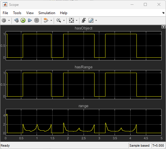
The hasObject output is a boolean value indicating if an object has been detected by the ultasonic sensor. The hasRange output is also a boolean value indicating if the closest distance from the detected object to the ultrasonic sensor is larger than the minimum-distance range of the sensor. In this example, the closest distance from the detected vehicles is always above the minimum-distance (0.03 m) as shown in the range output. These range values will be used to build a 2-D occupancy grid map in the next section.
Build a 2-D Occupancy Grid Map
occupancyMap (Navigation Toolbox) offer a simple yet robust way of representing an environment for robotic applications by mapping the continuous world-space to a discrete data structure. Individual grid cells can contain probabilistic information, where 0 indicates free-space, and 1 indicates occupied space. You can collect this information over time using ultrasonic sensor measurements and efficiently store it in the map. Each ultrasonic detection is converted to a vector of 2-D rays based on the distance measurement and the horizontal field of view. Since a single ultrasonic sensor can only measure the distance but not the orientation from the sensor to the closest objects, all the rays will have the same range.
% Create an empty occupancy grid map
mapWidth   = 60;
mapLength  = max(refPosesY(:,2))-min(refPosesY(:,2))+10; % in meters
resolution = 10; % 10 cells per meter
map        = occupancyMap(mapWidth,mapLength,resolution);

% Set the bottom-left corner of the map relative to the world frame
map.GridLocationInWorld = [min(refPosesX(1,2))-mapWidth/2, min(refPosesY(1,2))-5];

% Add detections to the map
for i = 1:numel(simOut.range)

    % Convert each detection to a vector of 2-D rays
    rayAngles = deg2rad(linspace(-horizontalFOV/2,horizontalFOV/2,100));

    % If an objected is detected, use the range output to build the map
    if simOut.hasObject(i)
        rayRanges = simOut.range(i) * ones(numel(rayAngles),1);
    else % No object is detected within the maximum detection range
        rayRanges = maxRange * ones(numel(rayAngles),1);
    end

    % Get ego vehicle pose
    vehiclePose = [simOut.location(i,1:2),simOut.orientation(i,3)];

    % Relative pose between the sensor and the ego vehicle
    relPose = [rightMirrorLoc(1)*cos(vehiclePose(3))+rightMirrorLoc(2)*sin(vehiclePose(3)),...
        rightMirrorLoc(1)*sin(vehiclePose(3))-rightMirrorLoc(2)*cos(vehiclePose(3)),...
        -pi/2];

    sensorPose = vehiclePose + relPose;
    insertRay(map,sensorPose,rayRanges,rayAngles,maxRange);
end

% Display the map
mapImage = show(map);
![Figure contains an axes object. The axes object with title Occupancy Grid, xlabel X [meters], ylabel Y [meters] contains an object of type image.](../../examples/driving/win64/BuildOccupancyMapUsingSimulation3DUltrasonicSensorExample_05.png)
The white area in the map represents the obstacle-free space. The black area represents the detected vehicles. The rest of the map in gray colorare the areas that have not been explored by the sensor yet. You can use this map for more advanced workflows, such as collision detection and path planning in more advanced applications such as parallel parking.
See Also
Simulation 3D Ultrasonic Sensor | Simulation 3D Scene Configuration | Simulation 3D Vehicle with Ground Following