Simulate Large Time Steps Using Trapezoidal Rule Solver for Real-Time FPGA Deployment
This example shows how to generate HDL code for a Simscape™ model by using the Trapezoidal Rule solver. You can then deploy the generated HDL code onto a Speedgoat® FPGA I/O module.
Setup and Configuration
1. To synthesize the generated HDL code, before you use HDL Coder™ to generate code, set up your synthesis tool path. For example, if your synthesis tool is Xilinx® Vivado®, install the latest version of Xilinx Vivado as shown in HDL Language Support and Supported Third-Party Tools and Hardware.
Then, set the tool path to the installed Xilinx Vivado executable by using the hdlsetuptoolpath function. For example, this command sets the synthesis tool path to point to your installed Vivado® Design Suite 2024.1 batch file:
hdlsetuptoolpath("ToolName","Xilinx Vivado",...
"ToolPath","C:\Xilinx\Vivado\2024.1\bin\vivado.bat")
2. For real-time simulation, set up the development environment and target computer settings. See Get Started with Simulink Real-Time (Simulink Real-Time).
3. To install your Speedgoat I/O Blockset and the Speedgoat - HDL Coder Integration packages, go to www.speedgoat.com/extranet, the Speedgoat® Customer Portal. Follow the instructions to download and install the Speedgoat I/O Blockset.
Use Trapezoidal Rule Solver to Simulate Large Time Steps
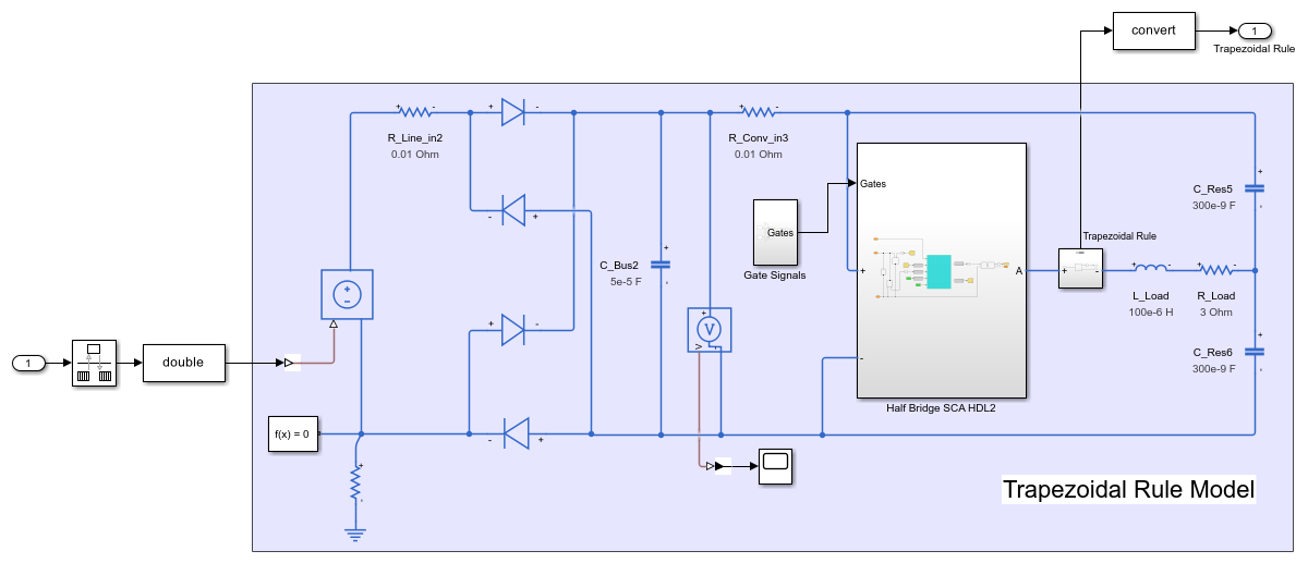
This example models an induction stovetop. The network model uses a half-bridge with subcycle averaging to generate alternating current to power induction coils. The model contains a network with fast RLC time constants. With the local solver set to Trapezoidal Rule, you can simulate the model with a larger time step and increased accuracy than with a Backward Euler local solver. Some electrical topologies such as wireless power transfer circuits cannot be accurately simulated with a Backward Euler solver with a time step larger than 100 ns. For real-time simulation, the Trapezoidal Rule solver lets you run these models with larger time steps (~1 μs) for specific hardware requirements.
The model in this example generates the necessary current to pass through the induction coils in an induction stovetop. The current is measured at the output.
Open the model from the MATLAB® command prompt.
ModelName = 'sschdl_trapezoidal_example';
open_system(ModelName)

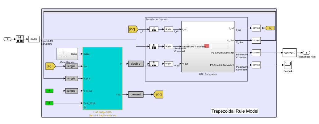
Open the Trapezoidal Rule Model subsystem
open_system('sschdl_trapezoidal_example/Trapezoidal Rule Model')
Simulate the model. To compare the results of Trapezoidal Rule local solver with the expected results from Baseline Model (using a variable step solver), open the Measured Current scope and observe the waveforms.
sim(ModelName);
open_system(['sschdl_trapezoidal_example' '/Measured Current'])
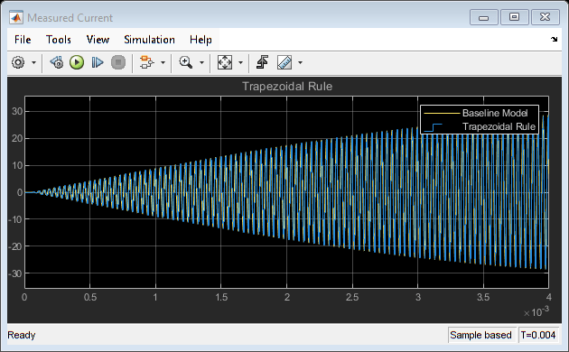
You can see that the two waveforms for the Baseline Model and Trapezoidal Rule Model overlap. There is no difference in the two results.
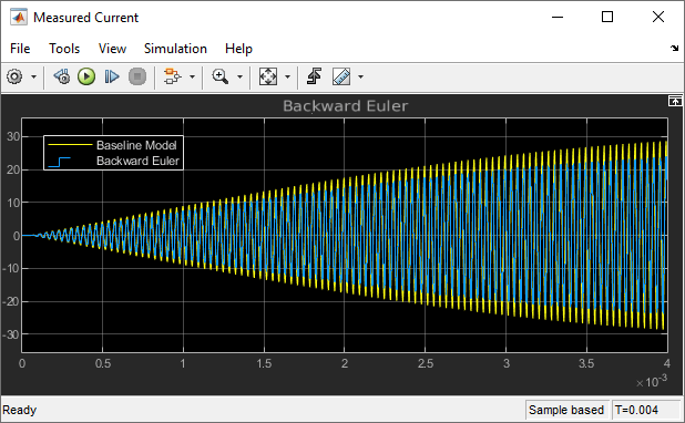
When you use the Backward Euler local solver with the same time step (1e-6 s) used with the Trapezoidal Rule local solver, the measured current is not correct. The Backward Euler local solver requires a smaller time step to provide accurate results for this model.
To continue with this example, right-click the Baseline Model, click Comment Out and save the model. On the Modeling tab, click Model Settings and select Model Settings from the drop-down menu. In the Solver window, specify the Solver selection options. From the Type list, select Fixed-step, and from the Solver list select discrete (no continuous states). Save the model.
Generate HDL Implementation Model and Validate HDL Algorithm
The Simscape HDL Workflow Advisor converts the Simscape plant model to an HDL-compatible implementation model from which you generate HDL code. To open the Advisor, run the sschdladvisor function for your model.
sschdladvisor('sschdl_trapezoidal_example')
To generate the HDL implementation model, in the Implementation model generation task drop-down list, right-click the Generate implementation model task, and then select Run to Selected Task from the list. After the task passes, you see a link to the HDL implementation model gmStateSpaceHDL_sschdl_trapezoidal_example.
To verify that the HDL implementation model matches the original Simscape model, generate a state-space validation model. In the Generate implementation model task, select the Generate validation logic for the implementation model check box and set the Validation logic tolerance to 1e-1. Then, run the task. See Validate HDL Implementation Model to Simscape Algorithm.
To modify the configuration parameter values for HDL code generation, navigate to gmStateSpaceHDL_sschdl_trapezoidal_example/Trapezoidal Rule Model/HDL Subsystem. Right-click the HDL Algorithm subsystem and select HDL Block Properties from the HDL Code list. In the HDL Properties dialog box, set the FlattenHierarchy to On. Click Apply and then click OK.
HDL Workflow Advisor
The HDL Workflow Advisor guides you through HDL code generation and the FPGA design process. Use the Advisor to:
Check the model for HDL code generation compatibility and fix incompatible settings.
hdlsetup('gmStateSpaceHDL_sschdl_trapezoidal_example')
Generate HDL code, test bench, and scripts to build and run the code and test bench.
Perform synthesis and timing analysis.
Deploy the generated code on SoCs, FPGAs, and Speedgoat I/O modules.
Generate FPGA Bitstream for Speedgoat Target Computer
Use HDL Workflow Advisor to Generate Simulink Real-Time Interface Model
1. Open the HDL implementation model, and then open the HDL Workflow Advisor for the implementation model.
open_system('gmStateSpaceHDL_sschdl_trapezoidal_example')
To open the HDL Workflow Advisor for a subsystem inside the model, use the hdladvisor function.
hdladvisor('gmStateSpaceHDL_sschdl_trapezoidal_example/Trapezoidal Rule Model')
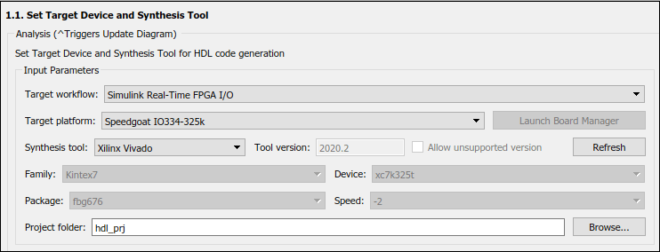
2. In the Set Target Device and Synthesis Tool task, specify Target workflow as Simulink Real-Time FPGA I/O and Target platform as Speedgoat IO334-325k.
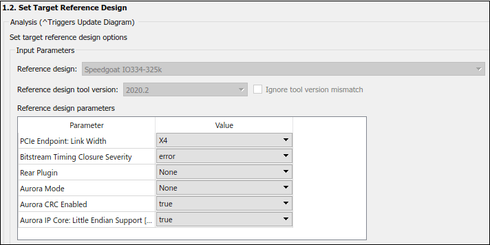
3. In the Set Target Reference Design task, select a value of X4 for the parameter PCIe lanes, and click the Run This Task button.
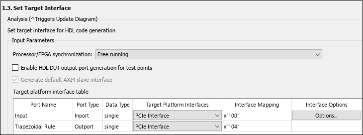
4. In the Set Target Interface task, map the input and output single data type ports to PCIe Interface and click the Run This Task button.
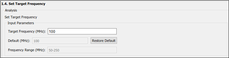
5. In the Set Target Frequency task, the default value of Target Frequency (MHz) is set to 100. For this example model, this value is same as default value.
6. In the HDL Code Generation task folder, click Set HDL Options then click the HDL Code Generation Settings button. This opens the Configuration Parameters dialog box. Under HDL Code Generation > Global Settings > Clock Settings, set the Oversampling factor to 1.
7. Right-click the Generate Simulink Real-Time Interface task, and select Run to Selected Task to generate the HDL IP core and FPGA bitstream.
Run Workflow Script to Generate Simulink Real-Time Interface Model
You can export the HDL Workflow Advisor settings to a script to expedite and automate your workflow. The script is a MATLAB® file that you run from the command line. You can modify and run the script, or import the settings into the HDL Workflow Advisor User Interface. See Run HDL Workflow with a Script.
This example shows how to run the HDL Workflow script. To generate a Simulink Real-Time Interface model, open and run this MATLAB script.
edit('hdlworkflow_trapezoidal_IO334')
%--------------------------------------------------------------------------
% HDL Workflow Script
% This script contains the model, target settings, interface mapping, and
% the Workflow Configuration settings for generating HDL code for the HDL
% implementation model generated for the Trapezoidal Example Model
% and for deploying the code to the FPGA on board the Speedgoat
% IO334-325K module.
%--------------------------------------------------------------------------

%% Load the Model
load_system('gmStateSpaceHDL_sschdl_trapezoidal_example');

%% Model HDL Parameters
%% Set Model 'gmStateSpaceHDL_ee_buck_converter_dc_motor_' HDL parameters
hdlset_param('gmStateSpaceHDL_sschdl_trapezoidal_example', 'HDLSubsystem', 'gmStateSpaceHDL_sschdl_trapezoidal_example/Trapezoidal Rule Model');
hdlset_param('gmStateSpaceHDL_sschdl_trapezoidal_example', 'Oversampling', 1);
hdlset_param('gmStateSpaceHDL_sschdl_trapezoidal_example/Trapezoidal Rule Model/HDL Subsystem/HDL Algorithm', 'FlattenHierarchy', 'on')
hdlset_param('gmStateSpaceHDL_sschdl_trapezoidal_example', 'ReferenceDesign', 'Speedgoat IO334-325k');
hdlset_param('gmStateSpaceHDL_sschdl_trapezoidal_example', 'SynthesisTool', 'Xilinx Vivado');
hdlset_param('gmStateSpaceHDL_sschdl_trapezoidal_example', 'SynthesisToolChipFamily', 'Kintex7');
hdlset_param('gmStateSpaceHDL_sschdl_trapezoidal_example', 'SynthesisToolDeviceName', 'xc7k325t');
hdlset_param('gmStateSpaceHDL_sschdl_trapezoidal_example', 'SynthesisToolPackageName', 'fbg676');
hdlset_param('gmStateSpaceHDL_sschdl_trapezoidal_example', 'SynthesisToolSpeedValue', '-2');
hdlset_param('gmStateSpaceHDL_sschdl_trapezoidal_example', 'TargetDirectory', 'C:\SscHdlTrapezoidalExample\hdl_prj\hdlsrc');
hdlset_param('gmStateSpaceHDL_sschdl_trapezoidal_example', 'TargetFrequency', 100);
hdlset_param('gmStateSpaceHDL_sschdl_trapezoidal_example', 'TargetPlatform', 'Speedgoat IO334-325k');
hdlset_param('gmStateSpaceHDL_sschdl_trapezoidal_example', 'Workflow', 'Simulink Real-Time FPGA I/O');

% Set SubSystem HDL parameters
hdlset_param('gmStateSpaceHDL_sschdl_trapezoidal_example/Trapezoidal Rule Model', 'ProcessorFPGASynchronization', 'Free running');

% Set Inport HDL parameters
hdlset_param('gmStateSpaceHDL_sschdl_trapezoidal_example/Trapezoidal Rule Model/Input', 'IOInterface', 'PCIe Interface');
hdlset_param('gmStateSpaceHDL_sschdl_trapezoidal_example/Trapezoidal Rule Model/Input', 'IOInterfaceMapping', 'x"100"');

% Set Outport HDL parameters
hdlset_param('gmStateSpaceHDL_sschdl_trapezoidal_example/Trapezoidal Rule Model/Trapezoidal Rule', 'IOInterface', 'PCIe Interface');
hdlset_param('gmStateSpaceHDL_sschdl_trapezoidal_example/Trapezoidal Rule Model/Trapezoidal Rule', 'IOInterfaceMapping', 'x"104"');

%% Workflow Configuration Settings
% Construct the Workflow Configuration Object with default settings
hWC = hdlcoder.WorkflowConfig('SynthesisTool','Xilinx Vivado','TargetWorkflow','Simulink Real-Time FPGA I/O');

% Specify the top level project directory
hWC.ProjectFolder = 'C:\SscHdlTrapezoidalExample\hdl_prj';
hWC.ReferenceDesignToolVersion = '2020.2';
hWC.IgnoreToolVersionMismatch = true;

% Set Workflow tasks to run
hWC.RunTaskGenerateRTLCodeAndIPCore = true;
hWC.RunTaskCreateProject = true;
hWC.RunTaskBuildFPGABitstream = true;
hWC.RunTaskGenerateSimulinkRealTimeInterface = true;

% Set properties related to 'RunTaskGenerateRTLCodeAndIPCore' Task

hWC.GenerateIPCoreReport = true;

% Set properties related to 'RunTaskCreateProject' Task
hWC.Objective = hdlcoder.Objective.None;
hWC.AdditionalProjectCreationTclFiles = '';
hWC.EnableIPCaching = true;

% Set properties related to 'RunTaskBuildFPGABitstream' Task
hWC.RunExternalBuild = false;
hWC.EnableDesignCheckpoint = false;
hWC.TclFileForSynthesisBuild = hdlcoder.BuildOption.Default;
hWC.CustomBuildTclFile = '';
hWC.DefaultCheckpointFile = 'Default';
hWC.RoutedDesignCheckpointFilePath = '';
hWC.MaxNumOfCoresForBuild = '';

% Validate the Workflow Configuration Object
hWC.validate;

%% Run the workflow
hdlcoder.runWorkflow('gmStateSpaceHDL_sschdl_trapezoidal_example/Trapezoidal Rule Model', hWC);

% Set the sample time in the final SLRT model
set_param('gm_gmStateSpaceHDL_sschdl_trapezoidal_example_slrt/Voltage Control Signal', 'SampleTime', '4e-6');
The last line of the script sets the sample time of the Voltage Control Signal block in the generated Simulink Real-Time Interface model to 4e-6.
Deploy Bitstream to Speedgoat IO334-325k Target
Prepare Simulink Real-Time Interface Model for Real-Time Simulation
Running the workflow script generates RTL code and IP core, creates a Vivado project, builds the FPGA bitstream, and then generates the Simulink Real-Time interface model.
The FPGA subsystem is automatically replaced in the real-time interface model with Speedgoat driver blocks to initialize the hardware and to interface with the FPGA during runtime.

Make sure you comment out any remaining Rate Transition blocks in the model to obtain a single rate model. All the blocks in the generated Simulink Real-Time model are executed on the CPU of the real-time system. The induction stovetop model is programmed in the bitstream and run at the faster rate on the FPGA.
Connect to Target Machine and Run Real-Time Simulation
The model can now be deployed onto the Speedgoat real-time target machine. Make sure that the Speedgoat real-time target machine is connected to the host computer and powered on.
You download the bitstream by using the Simulink Real-Time Explorer. To open the Simulink Real-Time Explorer, enter the command slrtExplorer. Alternatively, you can open the Explorer from the Real-Time tab of the Simulink Toolstrip.
slrtExplorer
The Simulink Editor displays the Real-Time tab for models that are configured for the speedgoat.tlc code generation target. Click the Connect to Target Computer button in the Simulink Real-Time tab to connect to the machine. Once connected, click the Run on Target button to deploy the model.
Simulink Real-Time automatically generates C code from your model by using Simulink Coder. The generated code and the bitstream for the FPGA are loaded onto the target machine, and model execution starts automatically.
See Also
Functions
Topics
- Generate and Validate HDL Code for Simscape Model
- FPGA-Based HIL Deployment of Simscape Model on Speedgoat FPGA I/O Module
- Deploy Simscape Grid Tied Converter Model to Speedgoat IO Module Using HDL Workflow Script
- Making Optimal Solver Choices for Physical Simulation (Simscape)
- Generate HDL Code for Nonlinear Simscape Models by Using Partitioning Solver