Map Matrices to ROM
In hardware design, efficiently managing constant data is important for optimizing resource use and timing. When implementing algorithms on FPGAs or ASICs using HDL Coder™, mapping matrices to read-only memory (ROM) can significantly improve design efficiency. Use ROM to store constant matrices, such as lookup tables.
Using MATLAB Code
To map a constant matrix to ROM:
Read one matrix element at a time. Use sequential access so HDL Coder recognizes the pattern for ROM inference.
The matrix size must be greater than or equal to the value specified for RAM mapping threshold in the HDL Workflow Advisor. If you specify a single integer to define this threshold, HDL Coder maps any delay or persistent array greater than that threshold bit size to RAM.
Matrix read accesses must not be in a feedback loop. Feedback loops imply dynamic data dependencies, which can hinder ROM inference.
If your MATLAB® code meets these requirements, HDL Coder inserts a no-reset register at the output of the matrix in the generated code. Many synthesis tools infer a ROM from this code pattern.
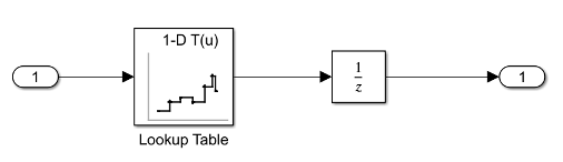
Using Simulink Blocks
HDL Coder does not provide a ROM block. You can build one by using these basic Simulink blocks:
Lookup Table block – Use a Lookup Table block to store the constant data you want in ROM. This block maps input indices to output values based on your matrix data.
Unit Delay block – Use a Unit Delay block to hold the output value. This setup mimics the behavior of a ROM by providing a stable output without reset capabilities.
To open an example that models a ROM block, type this command in the MATLAB Command Window:
openExample("hdlcoder/GettingStartedWithRAMAndROMInSimulinkExample",...
"supportingFile","hdlcoderrom.slx");
If you follow these guidelines, most synthesis tools implement the ROM using dedicated RAM blocks in an FPGA:
For an n-bit address, specify all 2n entries of the lookup table data. Otherwise, your synthesis tool may not map the generated code to RAM, and the code may not match the functionality of your Simulink® model.
Place the Lookup Table and Unit Delay blocks in the same model hierarchy.
Suppress the generation of reset logic for the Unit Delay block by setting the ResetType property to
nonein the HDL Block Properties dialog box.To ignore the initial simulation mismatch caused by suppressing the reset logic, set the model configuration parameter Ignore output data checking (number of samples) to
1.