Morphological Reconstruction
You can use morphological reconstruction to extract or enhance marked objects from an image. The image you want to enhance is the mask image. A second image, the marker image, is used to mark the regions to extract or emphasize. The peaks of the marker image act as seed pixels that spread out to fill in the mask image. Conceptually, you can think of this process as repeated dilations of the marker image.
Note
To learn how morphological reconstruction is implemented in the toolbox, see
imreconstruct.
This figure illustrates the concept in 1-D. Each successive dilation is constrained to lie underneath the mask. The final dilation is the reconstructed image.
Repeated Dilations of Marker Image, Constrained by Mask

If you change the marker image, the reconstructed image is different. In this figure, the right-most peak is suppressed in the marker image, and is therefore absent from the reconstructed image.
Morphological Reconstruction with Modified Marker Image

Morphological reconstruction is based on morphological dilation, but has these distinguishing characteristics:
Processing uses two images, a marker and a mask, rather than one image and a structuring element.
Because morphological reconstruction uses pixel connectivity, rather than a structuring element with a specific shape and size, the process maintains the shape and size of objects from the mask image. For more information on pixel connectivity, see pixel connectivity.
Processing continues until the image values stop changing.
You can control the result of a morphological reconstruction operation by modifying the marker image and the pixel connectivity.
Marker Image and Mask Image
Consider this 2-D grayscale mask image. It contains two primary regions,
represented by the blocks of pixels containing intensity values of
14 and 18. Most of the background pixels
have intensity values of 10, while some have values of
11.

To morphologically reconstruct this image, perform these steps:
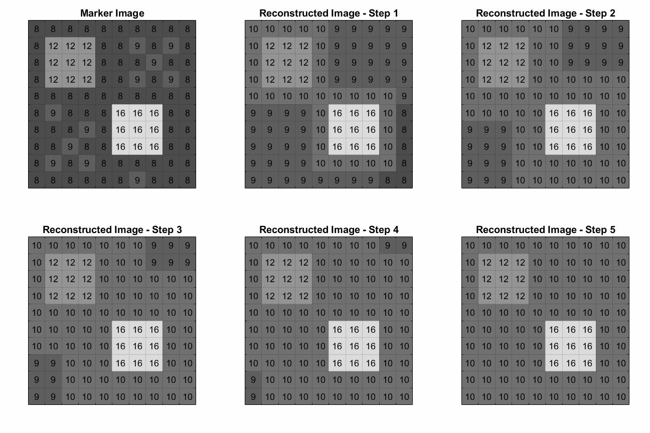
Create a marker image. Much like a structuring element in dilation and erosion, the characteristics of the marker image determine the processing performed in morphological reconstruction. The peaks in the marker image should identify the locations of objects in the mask image that you want to emphasize.
One way to create a marker image is to subtract a constant value from each pixel of the mask image. In this example, the marker image is created by subtracting
2from each pixel of the mask image.
Use the
imreconstructfunction to morphologically reconstruct the image.This animation shows the incremental changes in image values. At each step, the marker image is dilated, but the value of each pixel cannot exceed the corresponding value in the mask image.

In the final reconstructed image, smaller intensity fluctuations have been removed. Only peaks whose values are greater than surrounding pixels by at least 2 remain. This difference threshold corresponds to the value subtracted from the mask image to create the marker image. For more information about using morphological reconstruction to modify peaks in grayscale images, see Suppress Minima and Maxima.

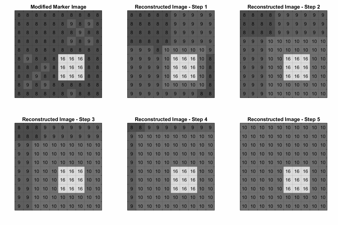
If you modify the marker image, the reconstructed image changes. You can remove
one of the peaks from the maker image by changing the values of the pixels in the
top-left peak from 12 to 8, to match the
background. The new reconstructed image has only one peak, at the location of the
corresponding peak in the marker image.

This animation shows the incremental changes in image values with the modified marker image.

Influence of Pixel Connectivity
During morphological reconstruction, peaks in the marker image incrementally spread to neighboring pixels. The specified pixel connectivity determines the boundaries of the neighborhood.
Consider this binary image of two diagonally adjacent squares. Based on an
8-connected neighborhood (the default value for the
imreconstruct function), the squares are a single
foreground object. Based on a 4-connected neighborhood, the squares are two separate
foreground objects.

This example performs morphological reconstruction using a marker image with one
single-pixel peak in the lower-right square. This is equivalent to the operation
performed by the bwselect function.
If you specify an 8-connected neighborhood, at each step the marker image peak pixels dilate to 8-connected pixels, limited to the values of the mask image. The image stops changing after three steps. The final reconstructed image includes both squares from the mask image.

If you perform morphological reconstruction with a 4-connected neighborhood, at each step the marker image peak pixels dilate to 4-connected pixels, limited to the values of the mask image. The image stops changing after two steps. The final reconstructed image includes only the lower-right square from the mask image.

This animation shows the incremental changes in the binary image with a pixel connectivity of eight versus a connectivity of four.

Applications of Morphological Reconstruction
You can use the imreconstruct function to perform
general morphological reconstruction to extract, emphasize, or suppress regions in a
mask image. Image Processing Toolbox™ also contains functions that use specialized morphological
reconstruction algorithms to accomplish specific image processing tasks.
The
imfillfunction suppresses dark regions to fill holes and perform flood-fill operations. For more information, see Flood-Fill Operations.The
imclearborderfunction suppresses light areas connected to the image border, which is useful for removing objects that are partially cut off at the edges of an image. Analogously, theimkeepborderfunction retains light areas connected to the image border and suppresses the rest.The
imextendedmax,imextendedmin,imhmax,imhmin, andimimposeminfunctions emphasize or suppress certain regional minima and maxima. For more information, see Find Image Peaks and Valleys.