Detect Unbalanced Motor by Using Neural Network
This example shows how to detect a mechanically unbalanced spinning motor by using a neural network (NN) developed using Deep Learning Toolbox™.
A rotating motor can vibrate if the center of mass of the motor-load does not align with the shaft. You can detect an unbalanced motor operation by using dedicated vibration sensors. However, because the phase currents of an unbalanced motor carry noise, you can also use current analysis to detect an unbalanced motor state. The cost effectiveness of the current analysis (due to the lack of actual physical sensors) makes it an excellent choice for detecting an unbalanced motor.
Detecting unbalance in a running motor requires modeling the relationship between the motor phase currents and the motor state. Such a physical model can be complex to develop. Therefore, the example demonstrates an alternate strategy of using a neural network-based model to detect motor unbalance.
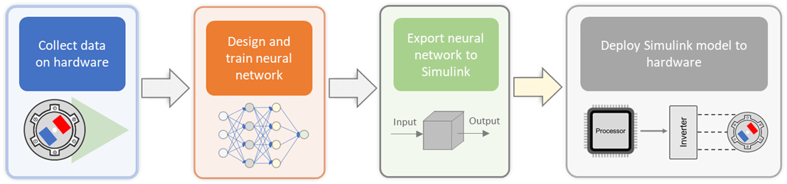
The example provides a workflow that you can use to design, train, and implement a neural network. The workflow includes these steps:
Collect data for training the neural network
Design and train the neural network
Export the neural network to a Simulink® model
Deploy the Simulink model to hardware
After you deploy the Simulink model to the hardware, you can test the model during both balanced and unbalanced states of a running motor.
Models
The example includes the model mcb_detect_unbalance that supports code generation.
Required MathWorks Products
Motor Control Blockset™
Embedded Coder®
C2000™ Microcontroller Blockset
Deep Learning Toolbox
Fixed-Point Designer™ (only needed for optimized code generation)
Required Hardware
This example supports the following hardware configuration:
LAUNCHXL-F28379D controller + BOOSTXL-DRV8305 inverter
You can customize the models in this example to use the other hardware boards supported by Motor Control Blockset™.
Emulating Unbalance
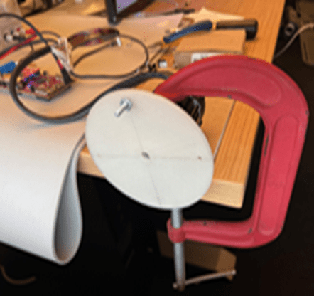
The example uses a hardware setup that emulates an unbalanced motor load to collect the data needed to train the neural network. The setup uses a plastic disk, which is fabricated to carry additional ballast, to represent an unbalance. The following figure shows the setup containing a motor attached with an emulated unbalanced load.
Collect Data on Hardware
Note: If you do not have the hardware setup to emulate the unbalanced motor load, you can skip this step and use the training and testing data available with this example.
You can collect the data required for training the neural network using a two-model (target and host model) approach that Motor Control Blockset examples use. You can deploy the target model mcb_detect_unbalance available with this example to the target controller hardware, and use the host model mcb_detect_unbalance_host.slx to control the motor operation. The target model simultaneously records the required signals to capture the training data.
Collect Data for Balanced Load
Remove the unbalanced motor load (plastic disk with nut and bolt fabricated into it) from the motor shaft of the hardware setup that you are using and follow this procedure.
1. Open the target model mcb_detect_unbalance and then open the Current Control subsystem.
2. Click the Detector subsystem and clear the Balance Detector checkbox (you can select this checkbox later during the testing phase).
3. Ensure that the hardware connections are complete. Load a sample program to CPU2 of LAUNCHXL-F28379D (for example, a program that operates the CPU2 blue LED by using GPIO31 (c28379D_cpu2_blink.slx)), to ensure that CPU2 is not mistakenly configured to use the board peripherals intended for CPU1. For more information about the sample program (model), see the Task 2 - Create, Configure and Run the Model for TI Delfino F28379D LaunchPad (Dual Core) section in Hardware Setup for C2000 Microcontroller Blockset (C2000 Microcontroller Blockset).
4. Click Build, Deploy & Start on the Hardware tab to deploy the target model to the hardware.
5. Open the host model mcb_detect_unbalance_host. Set the Debug signals button to Ia, Ib, Iq, Speed (to configure the host model to log the Ia, Ib, Iq, and speed signals).
For details about the serial communication between the host and target models, see Host-Target Communication.
6. In the model initialization script associated with the target model, specify the communication port using the variable target.comport. The example uses this variable to update the Port parameter of the Host Serial Setup, Host Serial Receive, and Host Serial Transmit blocks available in the host model.
7. Click Run on the Simulation tab to run the host model. The host model starts logging the signals immediately.
8. Change the position of the Start / Stop Motor switch to Start (to start running the motor). The motor starts running at the initial set speed of 500RPM.
9. Keep on increasing the speed by 500RPM until you reach 2000RPM. Keep the motor running at each incremented speed level for approximately 5 seconds.
10. After you reach the final speed of 2000 RPM, change the position of the Start / Stop Motor switch to Stop (to stop running the motor).
11. Click the Stop button on the Simulink toolstrip to stop host model simulation. Check if the MATLAB base workspace contains a variable named res that contains all the logged signals.
12. Run the MATLAB function transformLoggedData to extract the currents Ia, Ib, Iq and the speed v, and save them to the respective files using the provided file prefix:
transformLoggedData(res, 'myBalancedData')
Collect Data for Unbalanced Load
Connect the unbalanced load (plastic disk with a nut and bolt) to the motor shaft and follow the steps 1 to 11 as described in the previous section (Collect Data for Balanced Load).
Run the MATLAB function transformLoggedData to extract the currents Ia, Ib, Iq and the speed v, and save them to the respective files using the provided file prefix:
transformLoggedData(res, 'myUnbalancedData')
Note: When following these steps, replace the file names balancedData and unbalancedData with new names to avoid overwriting the prerecorded training data available with this example.
Prepare Collected Data
Use the preprocessLoggedData function to prepare the logged data for training, validating, and testing the neural network. The function returns three data structures:
trainData – This structure contains the data for training the neural network.
validData – This structure contains the data for validating the neural network during training.
testData – This structure contains the data for testing the trained neural network.
The function creates these structures by splitting the logged data for the balanced and unbalanced load conditions according to the ratios 0.70, 0.15, and 0.15.
The collected signals can have unwanted sections at the beginning and the end of the signal. The function records these sections before the motor starts and after the motor stops respectively. You can use the preprocessLoggedData function to visualize and trim these sections from the beginning and end of the recorded signals.
Run the preprocessLoggedData function to use the prerecorded training data available with the example.
[trainData, validData, testData] = preprocessLoggedData()
Optionally, run the function by using the names of the files you created (during data collection using your hardware setup) as input arguments.
[trainData, validData, testData] = preprocessLoggedData('myBalancedData', 'myUnbalancedData')
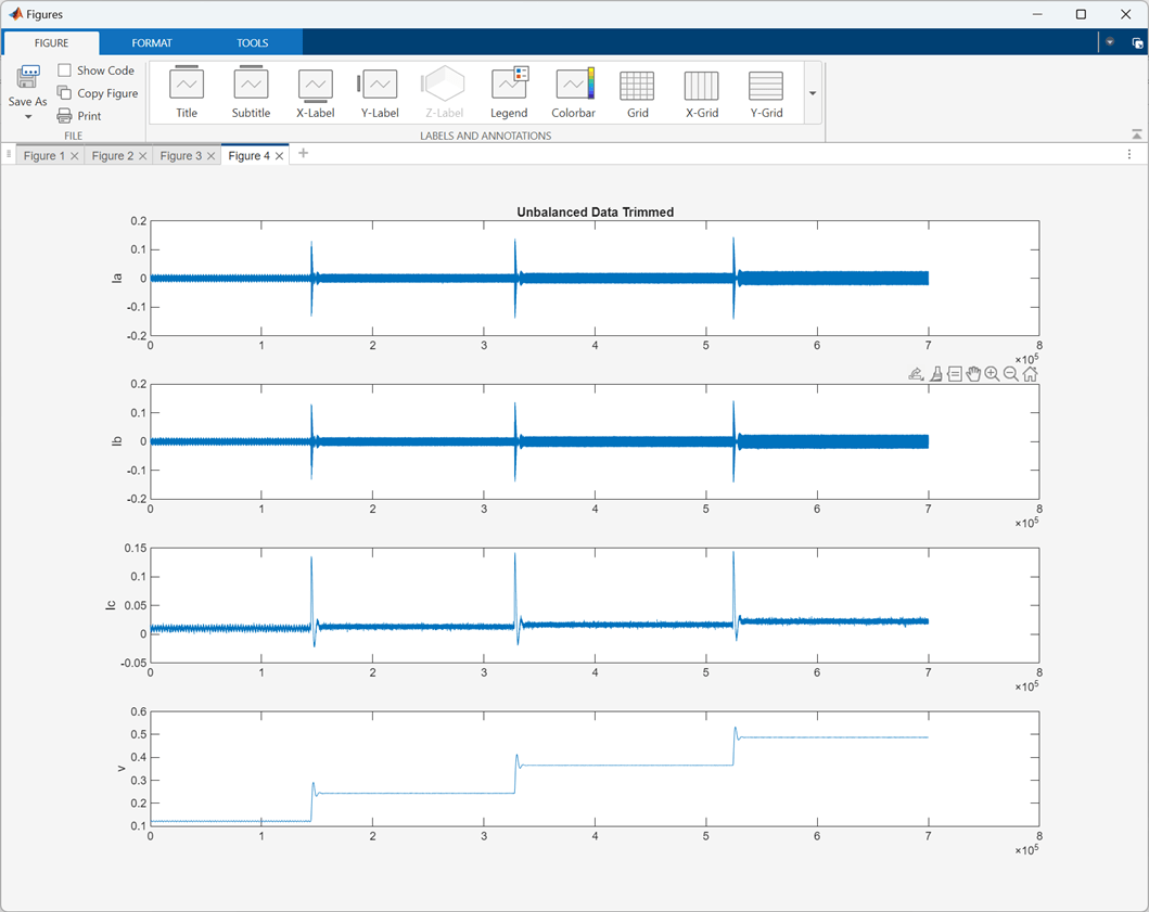
The following figure shows the unbalanced data signals after trimming when you use the training data available with this example along with the default trimming points. You can use the preprocessLoggedData function to select different trimming points.
Design, Train and Test Neural Network
Use the createNetwork function to define, train, and test the neural network. Run the function at the MATLAB command prompt by using the three previously obtained data sets as input arguments.
createNetwork(trainData, validData, testData)
The createNetwork function follows these three steps.
1. Design Neural Network
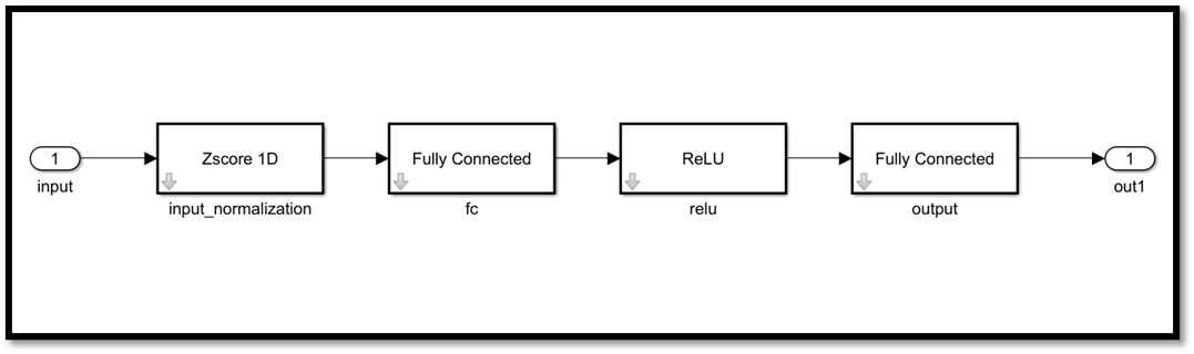
The first step is to select a neural network. This example uses a neural network with the following architecture.
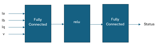
In the preceding figure:
Ia, Ib are the phase currents
Iq is the quadrature current
V is the motor speed
Status is the predicted motor status (either balanced or unbalanced)
The following code snippet shows how the createNetwork function defines the neural network layers.
layers = [
    featureInputLayer(4, 'Normalization', 'zscore')
    fullyConnectedLayer(10)
    reluLayer
    fullyConnectedLayer(1, 'Name', 'output') ];
2. Train Neural Network
The createNetwork utility function also trains the neural network. The following code snippet shows how the function trains and then saves the network.
options = trainingOptions("lbfgs", ...
    "LineSearchMethod", "backtracking",...
    "MaxIterations", 250, ...
    "GradientTolerance", 1e-9, ...
    "StepTolerance", 1e-9, ...
    "ValidationData", {valid.X, valid.Y}, ...
	 "ValidationPatience", 5);
myNet = dlnetwork(layers);
myNet = dlupdate(@double, myNet);
myNet = trainnet(trainData.X, trainData.Y, myNet, "mean-squared-error", options);
save('myNN', 'myNet')
When training of neural network is in progress, you can see the following output on the MATLAB command prompt:
    Iteration    TimeElapsed    TrainingLoss    ValidationLoss    GradientNorm    StepNorm
    _________    ___________    ____________    ______________    ____________    ________
            0       00:00:00                           0.46629
            1       00:00:01         0.35912                           0.33635     0.45645
           50       00:00:30         0.17055           0.16071       0.0020474     0.01836
          100       00:00:57         0.16228           0.15291       0.0045612     0.01639
          150       00:01:26         0.16026           0.15101       0.0058725    0.037007
          200       00:01:53         0.15946           0.15041       0.0042612     0.02199
          250       00:02:21         0.15914           0.15012      0.00099818   0.0040409

Training stopped: Max iterations completed
3. Test Neural Network
The createNetwork utility function also tests the network. The following code snippet shows how the function tests the network.
predictions = predict(myNet, xTest);
runningMeanPred = smooth(predictions, 1024, 'moving');
predProc = runningMeanPred > 0.5;
runningMeanTest = smooth(yTest, 1024, 'moving');
predTest = runningMeanTest > 0.5;
accuracy = sum(predProc == predTest) / numel(predTest);
disp(['Test Accuracy: ', num2str(accuracy*100), '%']);
Note: The neural network provides instantaneous prediction every 50 microseconds, which is too fast for human perception and may result in unrealistic prediction oscillations. Therefore, the example outputs a single prediction every 1024 samples.
After testing concludes, the function displays the following output on the MATLAB command prompt.
Test Accuracy: 98.4558%
Export Network to Simulink
After you train the neural network, the next step is to export it to a Simulink model. The example uses the exportNetworkToSimulink function from Deep Learning Toolbox to export the trained neural network (net) to the Simulink layers blocks so that you can use it for simulation and code generation.
Run the following command to execute the function:
exportNetworkToSimulink(net)
The function accepts the dlnetwork object net to create the Simulink layers blocks in a new Simulink model as shown in the following figure:
Use Network in Simulink Model
Copy the layers blocks to the Detector subsystem available in the target model as shown in the following figure.

Note: The subsystem Smooth Decision averages the output of the neural network over the window of 1024 samples.
Generate Code and Deploy Model to Target Hardware
Use the following procedure to generate code for the target model as well as to deploy the generated code to the hardware.
1. Ensure that you disconnect the unbalanced load (plastic disk with ballast) from the motor shaft and complete the hardware connections.
For details about hardware connections related to the LAUNCHXL-F28379D controller + BOOSTXL-DRV8305 inverter configuration, seeLAUNCHXL-F28069M and LAUNCHXL-F28379D Configurations.
2. Open the target model mcb_detect_unbalance and then open the Current Control subsystem. Click the Detector subsystem and select the Balance Detector checkbox.
3. The target model automatically computes the ADC (or current) offset values. To disable this functionality (enabled by default), update the variable inverter.ADCOffsetCalibEnable in the model initialization script to value 0 . Alternatively, you can compute the ADC offset values and update it manually in the model initialization scripts. For instructions, see Run 3-Phase AC Motors in Open-Loop Control and Calibrate ADC Offset.
4. Click Build, Deploy & Start on the Hardware tab to deploy the target model to the hardware.
5. Click the host model hyperlink in the target model to open the associated host model. For details about the serial communication between the host and target models, see Host-Target Communication.
6. In the model initialization script associated with the target model, specify the communication port using the variable target.comport. The example uses this variable to update the Port parameter of the Host Serial Setup, Host Serial Receive, and Host Serial Transmit blocks available in the host model.
7. In the host model, ensure that you set the button Debug signals to Ia, Ib, Speed, Status.
8. Right-click the signal connected to the Debug4 port of the Receive Target Data subsystem (motor status) and select Log Selected Signal.
9. Click Run on the Simulation tab to run the host model.
10. Change the position of the Start / Stop Motor switch to On, to start running the motor.
11. Open Simulink Data Inspector of the host model to monitor signal that represents the status of the motor.
12. Change the Reference Speed (RPM) value using the host model and monitor the status of the motor.
13. Use the Start / Stop Motor switch to stop the motor and then mount the unbalanced motor load (plastic disk with nut and bolt) to the motor shaft.
14. Use the Start / Stop Motor switch to start the motor. Change the motor speed using the host model and monitor the status of the motor.