Main Content

phased.NRRectangularPanelArray

5G antenna array described in 3GPP TR 38.901 specification

Since R2021a

Description

The phased.NRRectangularPanelArray System object™ creates a rectangular antenna array designed to meet the 3GPP TR 38.901 standard. This object models an antenna pattern generated by multiple panels in a rectangular layout. Each panel is a heterogeneous array consisting of co-located antenna elements. The default set of antenna elements is a pair of phased.NRAntennaElement antenna elements having +45° and -45° as the polarization slant angles. The default configuration of each panel is a 2-by-2 antenna configuration. You can also create an array using other types of elements. Elements and panels lie in the yz-plane.

To compute the response of the antenna element for specified directions:

  1. Create the phased.NRRectangularPanelArray object and set its properties.

  2. Call the object with arguments, as if it were a function.

To learn more about how System objects work, see What Are System Objects?

Creation

Description

example

array = phased.NRRectangularPanelArray creates an NR antenna panel array System object, array that follows the specification described in the 3GPP TR 38.901.

example

array = phased.NRRectangularPanelArray(Name,Value) creates an NR rectangular panel array object, array, with each specified property set to the specified value. You can specify additional name-value arguments in any order as (Name1,Value1,...,NameN,ValueN).

Properties

expand all

Unless otherwise indicated, properties are nontunable, which means you cannot change their values after calling the object. Objects lock when you call them, and the release function unlocks them.

If a property is tunable, you can change its value at any time.

For more information on changing property values, see System Design in MATLAB Using System Objects.

Array antenna elements, specified as a 1-by-2 cell array or 1-by-1 cell array. The default value is a 1-by-2 cell array containing two phased.NRAntennaElement antenna elements both with a selected PolarizationModel of 2. One element has a –45° polarization angle and the other has a +45° polarization angle defined by the PolarizationAngle property.

Sizes of element grid and panel grid, specified as a 1-by-4 vector of positive integer values. The first two entries represent the number of elements in a panel and the last two entries represent the number of panels in the array. The default value is one panel grid with a panel size of 2-by-2 elements.

Example: [2 2 2 2]

Data Types: double

Spacing between elements and between panels, specified as a 1-by-4 positive vector. The first two entries represent the spacing between elements within the panel and the remaining values represent the spacing between panels in the array. Spacing between panels is measured from the center of each panel. Units are in meters.

Example: [0.75 0.75 1.0 1.0]

Data Types: double

Set this property to true to treat each panel as a subarray. Each subarray is supported by a single RF chain if there is only one element at each position, or two RF chains if there are two elements at each position. Set this property to false when every element has its own RF chain.

Data Types: logical

Method of subarray steering, specified as 'None' or 'Custom'. When you set this property to 'Custom', the complex weights coefficient for each element in the array is specified as an input.

Example: 'Custom'

Data Types: char | string

Array element tapers, specified as a complex scalar or a length-N complex-valued vector of weights applied to each element in the sensor array. N is the number of elements in the array. If Taper is a scalar, identical weights are applied to each element. If Taper is a vector, each weight is applied to the corresponding array element.

Example: 1

Data Types: double
Complex Number Support: Yes

Usage

Description

example

RESP = array(FREQ,ANG) returns the array voltage response, RESP, at the operating frequencies specified in FREQ and in directions specified in ANG.

RESP = array(FREQ,ANG,V) also specifies the propagation speed V. This syntax applies when you set the EnablePanelArray property to true and the SubarraySteering property to 'None'.

example

RESP = array(FREQ,ANG,V,WS) also specifies the element weights, WS. Note that when the ElementSet property contains two elements, each panel contains two subarrays. To enable this syntax, set the EnablePanelArray property to true and the SubarraySteering property to 'Custom'.

Note

The object performs an initialization the first time the object is executed. This initialization locks nontunable properties and input specifications, such as dimensions, complexity, and data type of the input data. If you change a nontunable property or an input specification, the System object issues an error. To change nontunable properties or inputs, you must first call the release method to unlock the object.

Input Arguments

expand all

Operating frequency of the antenna element, specified as a nonnegative scalar or nonnegative, real-valued 1-by-L row vector. Frequency units are in Hz.

FREQ must lie within the range of values specified by the FrequencyRange or the FrequencyVector property of the element. Otherwise, the element produces no response and the response is returned as –Inf. Element objects use the FrequencyRange property, except for phased.CustomAntennaElement, which uses the FrequencyVector property.

Example: [1e8 2e6]

Data Types: double

Azimuth and elevation angles of the response directions, specified as a real-valued 1-by-M row vector or a real-valued 2-by-M matrix, where M is the number of angular directions. Angle units are in degrees. The azimuth angle must lie in the range –180° to 180°, inclusive. The elevation angle must lie in the range –90° to 90°, inclusive.

  • If ANG is a 1-by-M vector, each element specifies the azimuth angle of the direction. In this case, the corresponding elevation angle is assumed to be zero.

  • If ANG is a 2-by-M matrix, each column of the matrix specifies the direction in the form [azimuth;elevation].

The azimuth angle is the angle between the x-axis and the projection of the direction vector onto the xy-plane. This angle is positive when measured from the x-axis toward the y-axis. The elevation angle is the angle between the direction vector and xy-plane. This angle is positive when measured toward the z-axis. See the definition of Azimuth and Elevation Angles.

Example: [110 125; 15 10]

Data Types: double

Propagation speed, specified as a positive scalar. Units are in m/s.

Example: physconst('LightSpeed')

Dependencies

To enable this syntax, set the EnablePanelArray property to true and the SubarraySteering property to 'None'.

Data Types: double

Element weights within each subarray, specified as a complex-valued Nse-by-Ns matrix where Nse is the number of elements within each subarray. Each column of WS represents the weights applied to the elements of the corresponding subarray. Note that when the ElementSet property contains two elements, each panel contains two subarrays.

Dependencies

To enable this argument, set the EnablePanelArray property to true and the SubarraySteering property to 'Custom'.

Data Types: double
Complex Number Support: Yes

Output Arguments

expand all

Voltage response of the array, returned as a complex-valued M-by-L matrix. In this matrix, M represents the number of angles specified in ANG and L represents the number of frequencies specified in FREQ.

  • If the array does not support polarization, RESP has a size of N-by-M-by-L where N is the number of elements in the phased array. Each column contains the responses of the array elements for the corresponding direction specified in ANG. Each page of RESP contains the responses of the array for the given frequency specified in FREQ.

  • If the array supports polarization, RESP is a struct containing two fields, H and V. H represents the horizontal polarization of the array response and V represents the vertical polarization of the array. Each struct field is an N-by-M-by-L array whose columns contains the responses of the array elements for the corresponding direction and frequency.

Data Types: double

Object Functions

To use an object function, specify the System object as the first input argument. For example, to release system resources of a System object named obj, use this syntax:

release(obj)

expand all

beamwidthBeamwidth of NR rectangular panel array
collectPlaneWaveSimulate received plane waves at array
directivityDirectivity of NR rectangular panel array
getElementNormalNormal vectors for array elements
getElementPositionPositions of array elements
getNumElementsNumber of elements in an array and subarray
getNumSubarraysNumber of subarrays in panel array
getSubarrayPositionGet positions of NR panel array subarrays
getTaperArray element tapers
isPolarizationCapableArray polarization capability
patternBeam pattern NR rectangular panel array
patternAzimuthAzimuthal pattern NR rectangular panel array
patternElevationElevation pattern NR rectangular panel array
perturbationsPerturbations defined on array
perturbedArrayApply perturbations to phased array
perturbedPatternDisplay pattern of perturbed array
viewArrayView array geometry
stepRun System object algorithm
releaseRelease resources and allow changes to System object property values and input characteristics
resetReset internal states of System object

Examples

collapse all

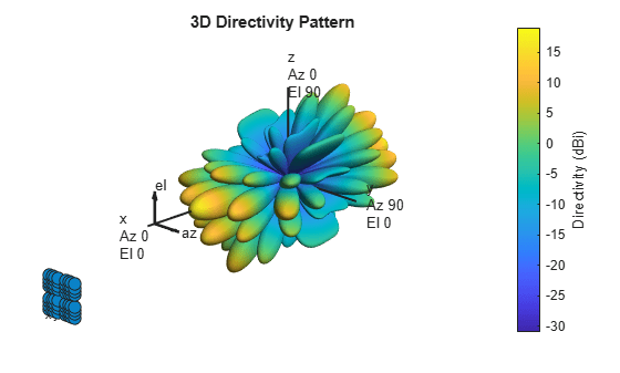
Construct a 5G antenna array where the grid is 2-by-2 and each panel is a 4-by-4 array. Each antenna element consists of two short-dipole antennas with different dipole axis directions. The antenna elements are spaced 1/2 wavelength apart and the panels are spaced 3 wavelengths apart. Plot the response pattern of the array assuming an operating frequency of 6 GHz.

c = physconst('LightSpeed');
fc = 6e9;
lambda = c/fc;
antenna1 = phased.ShortDipoleAntennaElement('AxisDirection','Z');
antenna2 = phased.ShortDipoleAntennaElement('AxisDirection','X');
array = phased.NRRectangularPanelArray('ElementSet', ...
        {antenna1, antenna2},'Size',[4, 4, 2, 2],'Spacing', ...
        [0.5*lambda, 0.5*lambda,3*lambda, 3*lambda]);
pattern(array,fc,'ShowArray',true)

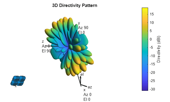
Use the Orientation property of pattern to change the orientation 80 along the x-axis, 30 along the y-axis and 60 along the z-axis.

pattern(array,fc,'Orientation',[80;30;60],'ShowArray',true)

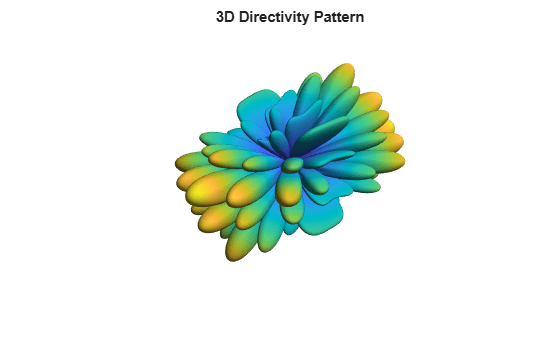
Disable the display of local coordinates and the colorbar.

pattern(array,fc,'ShowLocalCoordinate',false,'ShowColorBar',false)

Construct a 5G antenna array where the grid is 2-by-2 and each panel is a 3-by-2 array. The antenna elements are two phased.NRAntennaElement objects having polarization angles of +45 and -45 degrees. Find the response of the array at boresight, assuming an operating frequency of 6 GHz. The elements are spaced 1/2-wavelength apart and the panels are 3-wavelengths apart.

    c = physconst('LightSpeed');
    fc = 6e9;
    lambda = c/fc;
    array = phased.NRRectangularPanelArray('Size',[3, 2, 2, 2], ...
            'Spacing',[0.5*lambda,0.5*lambda,3*lambda,3*lambda]);
    resp = array(fc,[0;0])
resp = struct with fields:
    H: [48x1 double]
    V: [48x1 double]

Construct a 5G antenna array with panels on a 2-by-2 grid with each panel being a 4-by-4 array. Each antenna element consists of two short-dipole elements. Use each panel as a subarray. The elements are spaced 1/2 wavelength apart and the panels are spaced at 5/2 wavelengths. Plot the response of the array at 6 GHz. Assume the weights for each element within the subarray is unity.

c = physconst('LightSpeed');
fc = 6e9;
lambda = c/fc;
ant = phased.ShortDipoleAntennaElement;
array = phased.NRRectangularPanelArray(ElementSet={ant,ant}, ...
    Size=[4, 4, 2, 2], ...
    Spacing=[0.5*lambda,0.5*lambda,5*0.5*lambda,5*0.5*lambda], ...
    EnablePanelSubarray=true,SubarraySteering='Custom');

Display the array pattern.

pattern(array,fc,'ElementWeights',ones(16,8));

Compute the number of elements and the number of subarrays.

getNumElements(array)
ans = 128
getNumSubarrays(array)
ans = 8

Then get the subarray positions.

getSubarrayPosition(array)
ans = 3×8

         0         0         0         0         0         0         0         0
   -0.0625   -0.0625   -0.0625   -0.0625    0.0625    0.0625    0.0625    0.0625
    0.0625    0.0625   -0.0625   -0.0625    0.0625    0.0625   -0.0625   -0.0625

More About

expand all

References

[1] 5G: Study on channel model for frequencies from 0.5 to 100 GHz, 3GPP TR38.901 Version 14.0.0 Release 14.

Extended Capabilities

Version History

Introduced in R2021a

expand all