Main Content

richards

Convert lumped element circuit to distributed element circuit using Richards' transformation

Since R2021b

    Description

    example

    cktOut = richards(cktIn,opFreq) applies Richards' transformation on the circuit cktIn and returns the circuit object cktOut at the given reference frequency opFreq. In the cktOut all capacitors and inductors are replaced by electrical-length-based transmission line objects txlineElectricalLength.

    Note

    You can apply Richard's transformation only to circuits where all negative terminals of the ports share the same node.

    txOut = richards(LorCobj,opFreq) convert a capacitor or inductor LorCobj into an electrical-length-based transmission line object txOut at opFreq.

    example

    [txOut,nodes] = richards(LorCobj,opFreq) also returns a vector of suggested nodes nodes to connect txOut if LorCobj is connected to a circuit.

    [txOut,nodes] = richards(___,stubmode=stubType) specify the stub type of the output transmission line by using a name-value argument.

    Examples

    collapse all

    Create lowpass LC-Pi Chebyshev filter with the passband frequency of 1 GHz, passband attenuation of 0.5 dB, and filter order of 5.

    Fp = 1e9;          
    Ap = 0.5;          
    Ord = 5;           
    cktIn = rffilter("FilterType","Chebyshev","ResponseType","Lowpass","Implementation","LC Pi","PassbandFrequency", ...
        Fp,"PassbandAttenuation",Ap,"FilterOrder",Ord);
    opFreq = 1e9;

    Convert the lumped elements of the RF filter to a distributed element using Richards' transformation.

    cktOut = richards(cktIn,opFreq)
    cktOut = 
      circuit: Circuit element
    
        ElementNames: {'C_tx'  'L_tx'  'C_1_tx'  'L_1_tx'  'C_2_tx'}
            Elements: [1x5 txlineElectricalLength]
               Nodes: [0 1 2 3 4 5 6]
                Name: 'unnamed'
            NumPorts: 2
           Terminals: {'p1+'  'p2+'  'p1-'  'p2-'}


    Create an inductor with the inductance of 5 nH.

    LorCobj= inductor(5e-9);

    Create a circuit.

    ckt = circuit('new_circuit1');

    Add a resistor and the inductor you created earlier to the circuit.

    add(ckt,[1 2],LorCobj);
    add(ckt,[2 3],resistor(100));

    Set the ports and display the results.

    setports(ckt,[1 0],[3 0])
    disp(ckt)
      circuit: Circuit element
    
        ElementNames: {'L'  'R'}
            Elements: [1x2 rf.internal.circuit.RLC]
               Nodes: [0 1 2 3]
                Name: 'new_circuit1'
            NumPorts: 2
           Terminals: {'p1+'  'p2+'  'p1-'  'p2-'}
    

    Apply Richards' transformation to the inductor at 1 GHz and display nodes to connect the transmission line.

    [txOut,nodes] = richards(LorCobj,1e9)
    txOut = 
      txlineElectricalLength: ElectricalLength element
    
                      Name: 'L_tx'
                        Z0: 31.4159
                LineLength: 0.7854
        ReferenceFrequency: 1.0000e+09
               Termination: 'Short'
                  StubMode: 'Series'
                  NumPorts: 2
                 Terminals: {'p1+'  'p2+'  'p1-'  'p2-'}
    
    
    nodes = 1×4
    
         1     2     0     0


    The nodes in this example represent the nodes at which a 2-port transmission line representing the series L. The returned node value is set to -1 when a ground node cannot be determined from the circuit.

    Input Arguments

    collapse all

    Input RF circuit, specified as a circuit, lcladder, rffilter, or matchingnetwork object.

    Inductor or capacitor, specified as an inductor or capacitor object.

    Operating frequency at which the Richards' transformation is applied, specified as a positive scalar.

    Stub type of txOut, specified as a 'Series' or 'Shunt'.

    Output Arguments

    collapse all

    Output circuit, returned as a circuit object.

    Electrical-length-based transmission line, returned as a txlineElectricalLength object.

    Nodes to connect txOut, returned as a vector.

    Algorithms

    collapse all

    Richards' Transformation

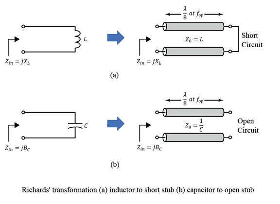
    This figure shows how Richards' transformation converts a circuit with capacitors and inductors into an abstract transmission line model [1].

    Richards' Transformation is applied to an inductor to get transformed to a short stub and to a capacitor to get transformed to an open stub.

    References

    [1] Pozar, David M. Microwave Engineering. 4th ed. Hoboken, NJ: Wiley, 2012.

    Version History

    Introduced in R2021b