filt2block
Generate Simulink filter block
Syntax
Description
filt2block(
generates a Discrete Filter (Simulink) block with
numerator coefficients, b,a)b, and denominator coefficients,
a.
If
ais a scalar or unspecified, thenfilt2blockgenerates a Discrete FIR Filter (Simulink) block.If
bhas up to three elements andahas two or three elements, then the function generates a Second-Order Section Filter (DSP System Toolbox) block. You must have DSP System Toolbox™ installed to create a Second-Order Section Filter block. Otherwise, specify the"subsystem"argument to generate a subsystem block that implements the filter using basic blocks.
filt2block( generates a
Simulink® block from a digital filter represented as Cascaded Transfer Functions (CTF) with numerator
coefficients B,A,"ctf")B and denominator coefficients
A. (since R2026a)
Note
Specify the "ctf" option to disambiguate CTF
numerator matrices B with six columns from
second-order section matrix inputs, sos, when you
specify A as a scalar or vector.
filt2block( generates a
Simulink block from a d)digitalFilter object,
d.
The function generates a Discrete FIR Filter (Simulink) block if
d is an FIR filter, a Discrete Filter (Simulink) block if
d is an IIR filter without any second-order sections, a
Second-Order
Section Filter (DSP System Toolbox) block if d is an IIR filter with
second-order sections, or a Subsystem (Simulink) block if
d is a digital filter cascade or has coefficients in
the CTF format.
filt2block( generates a Second-Order
Section Filter (DSP System Toolbox) block from an L-by-6 second-order
sections matrix, sos)sos. L is the number of
sections and must be greater than or equal to 2.
filt2block(___,
uses additional options specified by one or more name-value arguments.Name=Value)
Examples
Design a 30th-order FIR filter using the window method. Specify a cutoff frequency of π/4 rad/sample. Create a Simulink® block.
b = fir1(30,0.25); filt2block(b)

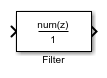
Design a third-order IIR Butterworth filter. Specify a cutoff frequency of π/4 rad/sample. Create a Simulink® block.
[b,a] = butter(3,0.25); filt2block(b,a)

Design a 30th-order FIR filter using the window method. Specify a cutoff frequency of π/4 rad/sample. Create a Simulink® block with a direct form I transposed structure.
b = fir1(30,0.25);
filt2block(b,FilterStructure="directFormTransposed")

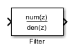
Design a 30th-order IIR Butterworth filter. Specify a cutoff frequency of π/4 rad/sample. Create a Simulink® block with a direct form I structure.
[B,A] = butter(30,0.25,"ctf"); filt2block(B,A,"ctf",FilterStructure="directForm1")

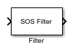
Design a 15th-order Butterworth filter with a cutoff frequency of π/5 rad/sample. Obtain the filter in biquad form and generate a Simulink® subsystem block from the second order sections.
[z,p,k] = butter(15,0.2);
sos = zp2sos(z,p,k);
filt2block(sos,"subsystem")

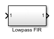
Generate a Simulink® subsystem block that implements an FIR lowpass filter using sum, gain, and delay blocks. Specify the input processing to be elements as channels by specifying FrameBasedProcessing as false.
b = fir1(8,0.5); filt2block(b,"subsystem",BlockName="Lowpass FIR", ... FrameBasedProcessing=false)

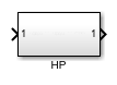
Design a highpass elliptic filter with normalized stopband frequency 0.45 and normalized passband frequency 0.55. Specify a stopband attenuation of 40 dB and a passband ripple of 0.5 dB. Implement the filter as a Direct Form II structure, call it "HP", and place it in a new Simulink® model.
d = designfilt("highpassiir",DesignMethod="ellip", ... StopbandFrequency=0.45,PassbandFrequency=0.55, ... StopbandAttenuation=40,PassbandRipple=0.5); filt2block(d,"subsystem",FilterStructure="directForm2", ... Destination="new",BlockName="HP")

Since R2026a
Design two digital filters with these specifications:
A lowpass FIR filter with normalized passband and stopband frequencies of 0.65 and 0.80, respectively. The passband ripple is 1 dB and the stopband attenuation is 50 dB.
A bandstop FIR filter with passband ripple of 1 dB and stopband attenuation of 50 dB. The normalized passband frequencies are 0.25 and 0.34. The normalized stopband frequencies are 0.36 and 0.45.
d1 = designfilt("lowpassfir", ... PassbandFrequency=0.65,StopbandFrequency=0.80, ... PassbandRipple=1,StopbandAttenuation=50); d2 = designfilt("bandstopfir", ... PassbandFrequency1=0.25,StopbandFrequency1=0.34, ... StopbandFrequency2=0.36,PassbandFrequency2=0.45, ... PassbandRipple1=1,StopbandAttenuation=50, ... PassbandRipple2=1);
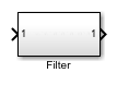
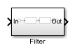
Cascade the lowpass FIR and bandstop FIR filters to form a digital filter cascade. Set the sample rate to 20 Hz.
d = cascade(d1,d2,SampleRate=20);
Implement the filter in a new Simulink® model.
filt2block(d)

Input Arguments
Transfer function coefficients, specified as vectors.
b and a represent the
numerator and denominator coefficients, respectively.
The filter coefficients are ordered in descending powers of z–1 with the first element corresponding to the coefficient for z0.
Note
If a(1) is not equal to 1,
then filt2block normalizes the filter
coefficients by a(1). In this case,
a(1) must be nonzero.
Example: b = fir1(30,0.25);
Example: [b,a] = butter(3,0.25,"high");
Data Types: single | double
Complex Number Support: Yes
Second order section matrix, specified as a K-by-6 matrix. Each row of the matrix contains the coefficients for a biquadratic rational function in z–1. The Z-transform of the kth rational biquadratic system impulse response is
.
The coefficients in the kth row of the matrix,
sos, are in this order:
.
The frequency response of the filter is its transfer function evaluated on the unit circle with z = ej2πf.
Note
If any element of sos(:,4) is not equal to
1, then filt2block
normalizes the filter coefficients by sos(:,4). In
this case, sos(:,4) must be nonzero.
Example: s = [2 4 2 6 0 2;3 3 0 6 0 0] specifies a
third-order Butterworth filter with normalized 3 dB frequency 0.5π
rad/sample.
Data Types: single | double
Complex Number Support: Yes
Digital filter, specified as a digitalFilter object. Use designfilt to generate a digital filter based on frequency-response
specifications.
Example: d = designfilt("lowpassiir",FilterOrder=3,HalfPowerFrequency=0.5)
specifies a third-order Butterworth filter with normalized 3 dB frequency 0.5π
rad/sample.
Cascaded transfer function (CTF) coefficients, specified as scalars, vectors, or
matrices. B and A list the numerator and
denominator coefficients of the cascaded transfer function, respectively.
B must be of size L-by-(m +
1) and A must be of size
L-by-(n + 1), where:
L represents the number of filter sections.
m represents the order of the filter numerators.
n represents the order of the filter denominators.
For more information about the cascaded transfer function format and coefficient matrices, see Specify Digital Filters in CTF Format.
Note
If any element of A(:,1) is not equal to
1, then filt2block normalizes the
filter coefficients by A(:,1). In this case,
A(:,1) must be nonzero.
Example: B = [2 4 2;3 3 0] and A = [6 0 2;6 0
0] specify a third-order Butterworth filter with normalized 3 dB
frequency 0.5π rad/sample.
Data Types: double | single
Complex Number Support: Yes
Scale values, specified as a real-valued scalar or as a real-valued vector with L + 1 elements, where L is the number of CTF sections. The scale values represent the distribution of the filter gain across sections of the cascaded filter representation.
The filt2block function applies a gain to the filter sections
using the scaleFilterSections function depending on how you specify
g:
Scalar — The function distributes the gain uniformly across all filter sections.
Vector — The function applies the first L gain values to the corresponding filter sections and distributes the last gain value uniformly across all filter sections.
Data Types: double | single
Name-Value Arguments
Specify optional pairs of arguments as
Name1=Value1,...,NameN=ValueN, where Name is
the argument name and Value is the corresponding value.
Name-value arguments must appear after other arguments, but the order of the
pairs does not matter.
Example: filt2block(d,"subsystem",BlockName="Lowpass
FIR",FrameBasedProcessing=true) generates a Simulink block that
implements a digital filter, d, where the block name is
"Lowpass FIR" and the input processing is
framed-based.
Filter structure, specified as a character vector or string scalar. Valid options for this argument depend on the filter type. The following table lists the valid filter structures for each filter type.
| Filter Type | Filter Structures |
|---|---|
| FIR |
Note
|
| IIR |
If
the filter has second-order sections, then the
function uses the
|
Destination for the Simulink filter block, specified as a character vector or string
scalar. You can add the filter block to your current model with
"current", add the filter block to a new model
with "new", or specify the name of an existing
model.
Example: filt2block([1 2 1],Destination="MyModel",BlockName="New
block")
Data Types: char | string
Block name, specified as a character vector or string scalar.
Data Types: char | string
Overwrite block, specified as a logical false or true.
If you use a value for BlockName that is the same as
an existing block, the value of OverwriteBlock
determines whether the block is overwritten.
Data Types: logical
Map coefficients to ports, specified as a logical false or true.
Data Types: logical
Coefficient variable names, specified as a cell array of character vectors or a string array.
This argument is applicable only when
MapCoefficientsToPorts is
true.
Valid options for this argument depend on the filter specifications. The following table lists the valid coefficient name for each filter specification.
| Filter Specification | Coefficient Names |
|---|---|
b | One-element array, consisting of the name for the numerator coefficients. Default:
|
| Two-element array, consisting of the name for the numerator and denominator coefficients. Default: |
sos | Two- or three-element array, consisting of one of these:
Default:
|
d |
|
| Two-element array, consisting of the name for the numerator and denominator coefficients.
Default:
|
{ | Three-element array, consisting of the name for the numerator coefficients, denominator coefficients, and scale values.
Default:
|
Data Types: cell | string
Option to choose between frame-based and sample-based processing, specified as one of these:
true—filt2blockcreates a block that performs frame-based processing.false—filt2blockcreates a block that performs sample-based processing.
To perform frame-based processing, you must have a DSP System Toolbox license. For more information, see Sample- and Frame-Based Concepts (DSP System Toolbox).
Data Types: logical
Remove zero-gain blocks, specified as a logical true or
false.
To specify this argument, you must also specify the
"subsystem" argument in the
filt2block function call.
Data Types: logical
Replace unity-gain blocks with direct connection, specified as a logical
true or false.
To specify this argument, you must also specify the
"subsystem" argument in the
filt2block function call.
Data Types: logical
Replace negative unity-gain blocks with a sign change at the nearest block, specified as a
logical true or false.
To specify this argument, you must also specify the
"subsystem" argument in the
filt2block function call.
Data Types: logical
Replace cascaded delays with a single delay, specified as a logical true or
false.
To specify this argument, you must also specify the
"subsystem" argument in the
filt2block function call.
Data Types: logical
More About
Partitioning an IIR digital filter into cascaded sections improves its numerical stability and reduces its susceptibility to coefficient quantization errors. The cascaded form of a transfer function H(z) in terms of the L transfer functions H1(z), H2(z), …, HL(z) is
You can specify digital filters in the CTF format for analysis, visualization, and signal
filtering. Specify a filter by listing its coefficients B and
A. You can also include the filter scaling gain across sections by
specifying a scalar or vector g.
When you specify the coefficients as L-row matrices,
it is assumed that you have specified the filter as a sequence of L cascaded transfer functions, such that the full transfer function of the filter is
where m ≥ 0 is the numerator order of the filter and n ≥ 0 is the denominator order.
If you specify both B and A as vectors, it is assumed that the underlying system is a one-section IIR filter (L = 1), with B representing the numerator of the transfer function and A representing its denominator.
If B is scalar, it is assumed that the filter is a cascade of all-pole IIR filters with each section having an overall system gain equal to B.
If A is scalar, it is assumed that the filter is a cascade of FIR filters with each section having an overall system gain equal to 1/A.
Note
If you have an overall scaling gain or multiple scaling gains factored out from the
coefficient values, you can specify the coefficients and gain as a cell array of the form {B,A,g}. Scaling filter sections is especially important when you work with
fixed-point arithmetic to ensure that the output of each filter section has similar
amplitude levels, which helps avoid inaccuracies in the filter response due to limited
numeric precision.
The gain can be a scalar overall gain or a vector of section gains.
If the gain is scalar, the value applies uniformly to all the cascade filter sections.
If the gain is a vector, it must have one more element than the number of filter sections L in the cascade. Each of the first L scale values applies to the corresponding filter section, and the last value applies uniformly to all the cascade filter sections.
If you specify the coefficient matrices and gain vector as
it is assumed that the transfer function of the filter system is
References
[1] Lyons, Richard G. Understanding Digital Signal Processing. Upper Saddle River, NJ: Prentice Hall, 2004.
Version History
Introduced in R2013aThe filt2block function supports inputs in the cascaded
transfer function (CTF) format.
MATLAB Command
You clicked a link that corresponds to this MATLAB command:
Run the command by entering it in the MATLAB Command Window. Web browsers do not support MATLAB commands.
Seleccione un país/idioma
Seleccione un país/idioma para obtener contenido traducido, si está disponible, y ver eventos y ofertas de productos y servicios locales. Según su ubicación geográfica, recomendamos que seleccione: .
También puede seleccionar uno de estos países/idiomas:
Cómo obtener el mejor rendimiento
Seleccione China (en idioma chino o inglés) para obtener el mejor rendimiento. Los sitios web de otros países no están optimizados para ser accedidos desde su ubicación geográfica.
América
- América Latina (Español)
- Canada (English)
- United States (English)
Europa
- Belgium (English)
- Denmark (English)
- Deutschland (Deutsch)
- España (Español)
- Finland (English)
- France (Français)
- Ireland (English)
- Italia (Italiano)
- Luxembourg (English)
- Netherlands (English)
- Norway (English)
- Österreich (Deutsch)
- Portugal (English)
- Sweden (English)
- Switzerland
- United Kingdom (English)