Model RF Components
Add RF Blocks to a Model
You can include blocks from the RF Blockset™ Equivalent Baseband Physical and Mathematical libraries in a Simulink® model. For more information on the libraries and the available RF blocks, see RF Blockset Equivalent Baseband Libraries.
This section contains the following topics:
Input Signal Requirements
Most RF Blockset Equivalent Baseband blocks only support complex single-channel signals. The signals can be either sample-based or frame-based. The following blocks have this requirement:
All Physical blocks
Mathematical Amplifier and Mixer blocks
You can model the effect of these components on a multichannel signal as follows:
How to Add RF Blocks to a Model
To add RF blocks to a Simulink model:
Type
rflibat the MATLAB® prompt to open the RF Blockset Equivalent Baseband library.Navigate to the desired library or sublibrary.
Drag instances of RF Blockset Equivalent Baseband blocks into the model window using the mouse.
Note
You can also access RF Blockset Equivalent Baseband blocks and other Simulink blocks from the Simulink Library Browser window. Open this window by typing
slLibraryBrowser at the MATLAB prompt. Add blocks to the model by dragging them from this
window and dropping them into the model window.
Connect Model Blocks
You follow the same procedure for connecting RF Blockset Equivalent Baseband blocks as for connecting Simulink blocks: you click a port and drag the mouse to draw a line to another port on a different block.
You can only connect blocks that use the same type of signal. Physical library blocks use different types of signals than Mathematical library blocks, and are represented graphically by a different port style. Therefore, you can freely connect pairs of Mathematical modeling blocks. You can also freely connect pairs of Physical modeling blocks. However, you cannot directly connect Physical blocks to Mathematical blocks. Instead, you must use the Input Port and Output Port blocks to bridge them.
For more information on the Physical and Mathematical libraries, including how to open the libraries and a description of the available blocks, see Overview of RF Blockset Equivalent Baseband Libraries.
This section contains the following topics:
Connect Mathematical Blocks
The Mathematical library blocks use the same input and output ports as standard Simulink blocks. These ports show the direction of the signal at the port, as shown in the following diagram.

Similar to standard Simulink blocks, you draw lines between the ports of the Mathematical modeling blocks, called signal lines, to represent signals that are inputs to and outputs from the mathematical functions represented by the blocks. Therefore, you can connect Simulink, DSP System Toolbox™, and RF Blockset Equivalent Baseband mathematical blocks by drawing signal lines between their ports.
You can connect a port to multiple ports by branching the signal line, or you can leave a port unconnected.
Connect Physical Blocks
The Physical library blocks have specialized connector ports. These ports only represent physical connections; they do not imply signal direction.
The lines you draw between the physical modeling blocks, called connection lines, represent physical connections among the block components. Connection lines appear as solid black when connected and as dashed red lines when either end is unconnected.
You can draw connection lines only between the connector ports of physical modeling blocks. You cannot branch these connection lines. You cannot leave connector ports unconnected.
Bridge Physical and Mathematical Blocks
The blockset provides the Input Port and Output Port blocks to connect the physical and mathematical parts of the model. These blocks convert mathematical signals to and from the physical modeling environment.
The Input Port and Output Port blocks have one of each kind of connector port: a standard Simulink style input port and a physical modeling port. These ports are shown in the following figure:
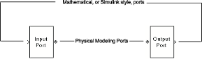
The Input Port and Output Port blocks must bound a physical subsystem to connect it to the mathematical part of a model.
For example, a simple RF model of a microstrip transmission line might resemble the following figure.
The Microstrip Transmission Line block uses an Input Port block to get its white noise input from a Random Source block, and an Output Port block to pass its output to a Spectrum Scope block. The Random Source and Spectrum Scope blocks are from DSP System Toolbox library.
For information on how RF Blockset Equivalent Baseband software converts mathematical signals to and from the physical modeling environment, see Convert to and from Simulink Signals.
See Also
Input Port | Output Port | Microstrip Transmission Line