Create Simulink Behavior Models
Implement the functionality of component functions defined in the architecture model from the previous step using Simulink® behavior models.
To open the completed model, run this command.
open("EVPwrCntrllrEMSysFinal.slx");Create Behavior Model for Service Components
Create the Simulink behavior models for the service components
VehicleDynamics_ServiceCmp and
BatteryManagementSystem_ServiceCmp, which use client-server
communication. Use Simulink export-function models to define and implement the component
behavior.
To create a Simulink behavior, right-click a service component and select Create Simulink Behavior.
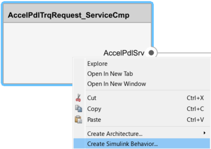
In the Create Simulink behavior dialog box, set Type to
Model Reference:
                                Export-Function
. Specify a filename and location to save the template model. Click OK.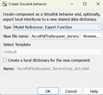
The template model subsystem includes the service interface created in System Composer™.
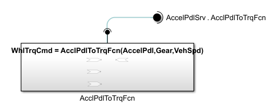
Define the service in the model by implementing the service component algorithm inside the Simulink Function block.
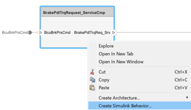
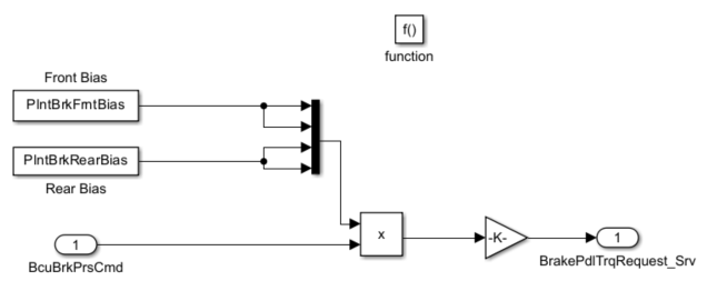
Create the Simulink behavior model for the
BrakePdlTrqRequest_ServiceCmp service component, which uses
sender-receiver communication.
In the Modeling tab in the toolstrip, open the Functions Editor.
Click the
BrakePdlTrqRequest_ServiceCmpcomponent box.In the Functions Editor, click the add
 button to add a function to the
software component.
button to add a function to the
software component.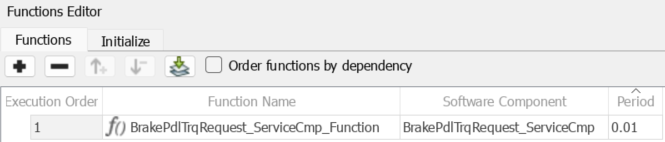
Right-click the component and select Create Simulink Behavior.
In the Create Simulink behavior dialog box, set Type to
Model Reference:
                                Export-Function
. Specify a filename and location to save the template model. Click OK.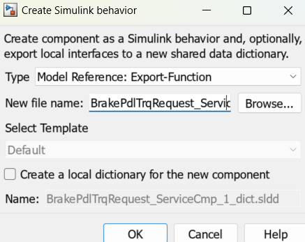
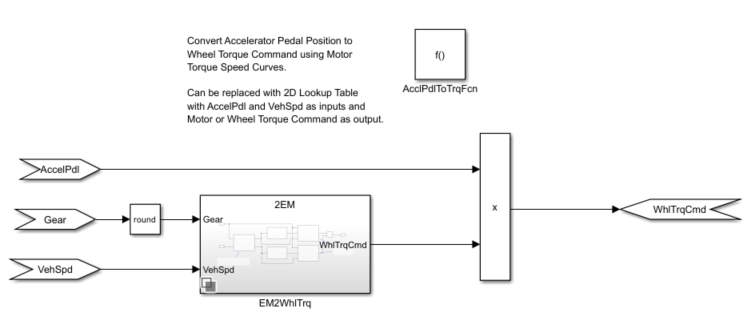
Open the template model subsystem.
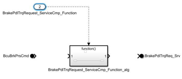
Add the algorithm for the service component functionality inside the Function-Call Subsystem block.
You can find the completed service component behavior models for this example in
the CreateSimulinkBehaviorModel/ServiceComponent folder.
Create Behavior Model for the Client Component
Create the behavior model for the Energy Management client component.
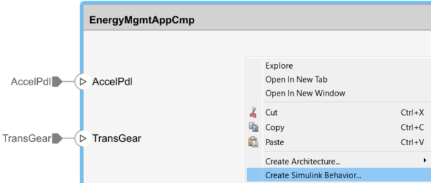
Right-click on the component and select Create Simulink Behavior.
In the Create Simulink behavior dialog box, set Type to
Model Reference:
                                Export-Function
. Specify a filename and location to save the template model. Click OK.
Open the model template.
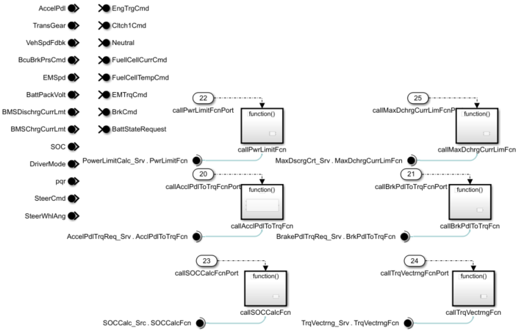
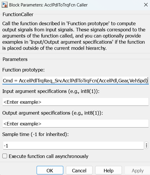
In the component behavior model, subsystems are created for each service that implements client-server communication. Each subsystem contains a Function Caller block.
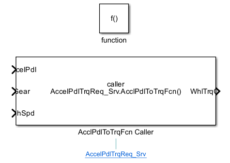
The Function prototype parameter is set according to the function prototype definitions added to the Interface Editor in the previous step.
Add the algorithm for the component functionality to the Simulink behavior model.
In this example, the algorithm needed to generate brake and torque commands is added to the Simulink behavior model.
Connect the service component function call inputs and outputs to the client component.
In this example, the service component function calls are grouped in pre-algorithm and post-algorithm subsystems and connected to the client component to match the original software intent.
Note
This example creates the behavior model for the client component using an export-function model. When implementing a call to a synchronous service, you can also use a rate-based model. For more information, see Implement Behavior of Functions Using Simulink (System Composer).
In this high-level overview of the connected subsystems, the pre-algorithm and post-algorithm subsystems are highlighted in blue, and the
Energy Managementsubsystem is highlighted in green.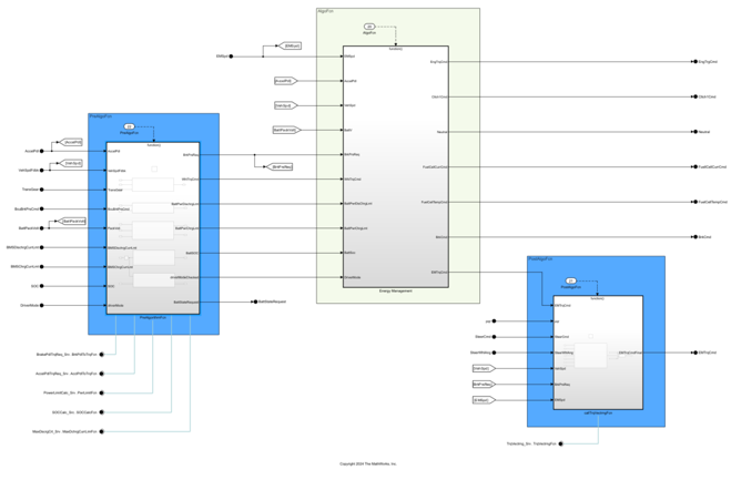
Specify the Sample time (-1 for inherited) parameter for each function-call subsystem input port to
0.01.Change the execution order of the functions in the Functions Editor so that
BrakePdlTrqRequest_ServiceCmpis the first function to execute.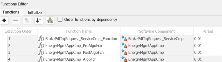
You can find the completed application component behavior model for this example
in the CreateSimulinkBehaviorModel/ApplicationComponent
folder.
See Also
Topics
- System Composer Concepts (System Composer)
- Service Interfaces Overview (System Composer)
- Author Software Architectures (System Composer)
- Create Rate-Based Model