System Architecture and Functionality
Best Practices for Model Composition and Components
A modular, scalable, and reusable architecture makes it easier to maintain your system when implementing updates. System Composer™ is a widely used tool for design and development of system and software architecture.
Component-based modeling is the process of breaking down a complex system model into smaller, manageable components. Each component represents a specific functionality or behavior of the system. For information, see Component-Based Modeling.
For more information on best practices for component based modeling, see Component-Based Modeling in Simulink.
Software Architecture Modeling
System Composer allows you to allocate requirements while refining an architecture model for design and simulation in Simulink®. To get started with System Composer, see Compose and Analyze Systems Using Architecture Models (System Composer). Consider using System Composer when your team has these objectives:
Building architecture models with interfaces and components and establishing relationships via model-to-model allocation
Behaviour modeling via sequence diagrams, state charts, or Simulink models
Defining execution order of component functions
Performing trade studies, investigating specific design concerns, capturing properties via stereotyping, and producing interface control documents
This workflow uses a model reference. The model is built in a flat hierarchy, which creates fewer dependencies than a tall hierarchy and enhances parallel build performance. You can componentize a model at the architecture level as well as at the design level. This section describes best practices for model composition during the design stage of the BMS model.
Steps to Create a BMS Software Architecture Model
Follow these steps to create a battery management system and software architecture model using System Composer.
Open new System Composer architecture model.
Add Subsystems as Model Components
Add subsystems as model components to meet the requirements you have defined.
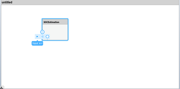
You can manually include the input and output interfaces of the BMS in the architecture diagram at the initial stage. Pause on the component boundary to add the ports and then click the added port to configure it as an input or output port.
Name each output and input port according to your requirements.
Follow these steps for all subsystems and connect the outputs to the inputs.
Model the ports at the system boundary level. In the BMS, external sources provide the
StateRequestandSensorsinputs, while the BMS sendsBMS_InfoandBMS_Cmdas outputs to external modules.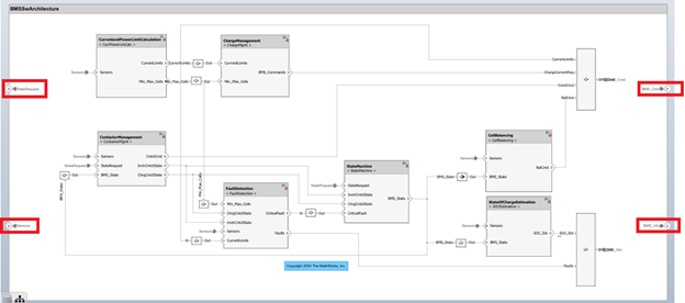
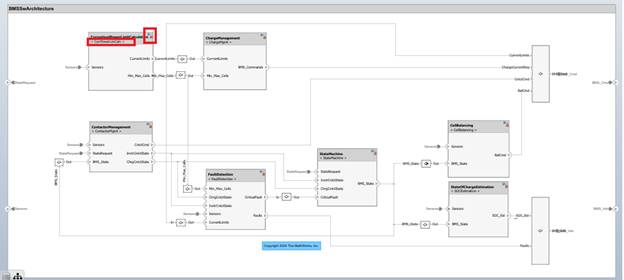
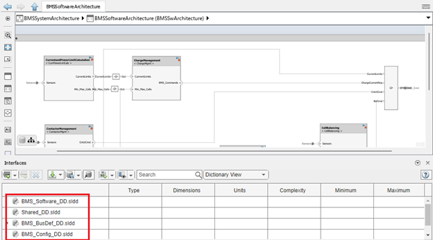
Link each component in the architecture to the independent Simulink models that you created at the design stage using model references. The name of the referenced model is circled in red in this figure.
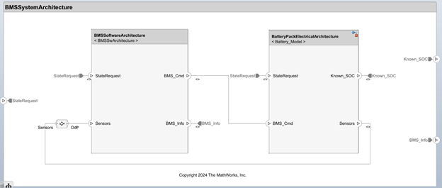
Battery Pack and System Architecture Modeling
Model the battery pack electrical architecture by following the previously mentioned steps. You can design the battery pack using the
BatteryPackDesignScript.mlxscript or the Battery Builder (Simscape Battery) app. For more details, see BMS Design.Model the system architecture by combining the battery plant model and the BMS controller model.
Data Management and Simulation
Check that the Simulink data dictionary used for data management in each Simulink model is available in the Interface Editor (System Composer).
Simulate the model and check that the architecture meets your requirements. Copy and paste these commands in the Command Window after you have loaded the
UseMBDtoBuildaBMSproject using Battery Management System Project.open('BMSSwArchitecture.slx'); %Open the software architecture model sim("BMSSwArchitecture.slx"); open('BMSSystemArchitecture.slx'); %Open the system architecture model