Use Model-Based Design to Build a Battery Management System
R2026bThis project shows a step-by-step model-based design (MBD) workflow for building a battery management system (BMS) controller. The project uses a lithium-ion Nickel-Manganese-Cobalt (NMC) battery pack and supports three plant fidelity levels (Lumped, Grouped, Detailed) so you can iterate quickly during development and validate at high fidelity before deployment.
The BMS controller is decomposed into three main components:
State Machine — Supervisory state machine (Standby, Driving, Charging, Fault)
Cell Monitoring and Balancing — State of charge (SOC) estimation and passive cell balancing
System Control and Protection — Fault detection, contactor management, and current/power limits
The BMS plant represents the physical battery system using Simscape™ components, including the battery pack, pre-charge circuit, charger, and drive load.
This workflow walks through six steps, from project setup through system-level verification with Simulink® Test™.
Workflow Steps
Click each box in the flow chart for more detail.
Set Up File Management System — Organize design files in a MATLAB® project.
Author and Import Requirements — Author requirements and import them into the Requirements Editor.
Manage Design Data — Partition parameters into referenced data dictionaries.
Develop Architecture Models — Decompose the system into components using System Composer™.
Connect to Model-Based Design — Link behavior models to architecture components.
Verify and Validate System — Test at component, architecture, and system levels.
Battery Management System Project
Click the open button to load the project to your working folder.
openProject('UseMBDtoBuildaBMS/UseMBDtoBuildaBMS.prj');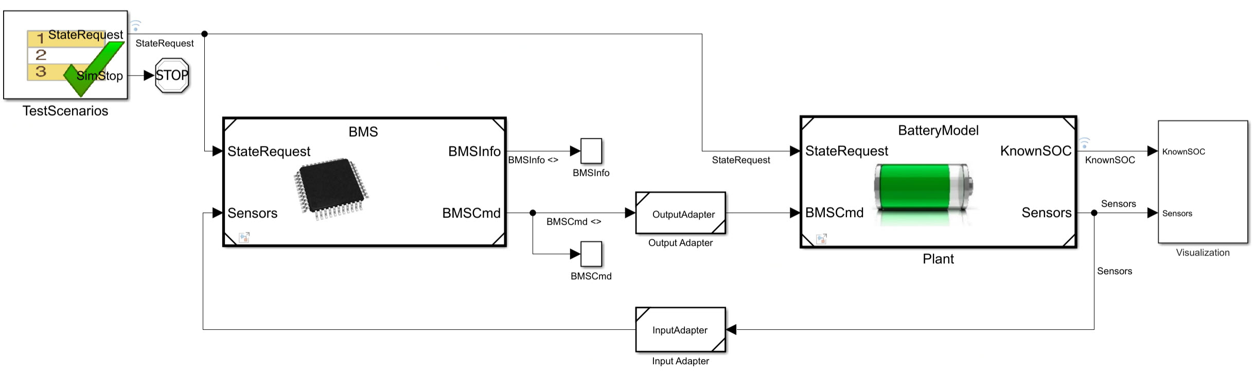
See Also
Topics
- Project Management
- Scale Up Simulink Models
- Author Architecture Models (System Composer)

