Using Resettable Subsystems
The Resettable Subsystem block is a Subsystem block preconfigured as a starting point for creating a subsystem that resets the block states each time the Reset port receives a trigger signal.
The following sections describe behavior of resettable subsystem and compare it with a subset of Simulink® blocks which have Reset ports or other ports that can be configured to behave like Reset ports.
Behavior of Resettable Subsystems
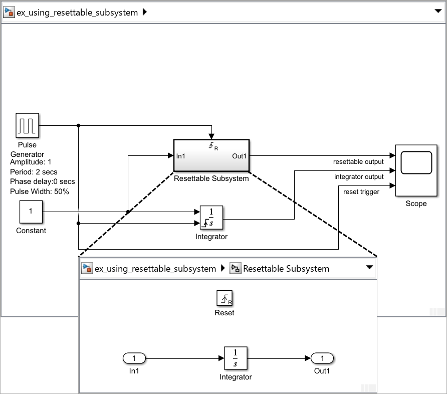
This model shows that the behavior of block reset ports and resettable subsystems is the same. A resettable subsystem enables you to reset the states of all blocks inside it. In this model, the resettable subsystem contains an integrator block that is configured similar to the root-level Integrator block, but the block does not have a reset port. The subsystem resets the states of the integrator block inside it in the same manner as the reset port of the Integrator block.

You can see this behavior by running the model and viewing the output in the Scope block. You can observe the following in the scope:
reset triggersignal represents the signal at the Reset port.At the rising edge of the
reset triggersignal, both the resettable subsystem and the Integrator block reset the Integrator block state to its initial condition (in this case 0).Between every two rising edges of the
reset triggersignal, both the resettable subsystem and the Integrator block execute. The output from the resettable subsystem and the Integrator block are represented in the scope byresettable outputandintegrator outputsignal respectively. As shown by the signals, both the outputs are same.

Using resettable subsystems over other methods of resetting states of your block or subsystem has these advantages:
When you want to reset the states of multiple blocks in a subsystem, displaying and connecting the reset port of each block is cumbersome and makes the block diagram hard to read. Instead, place all the blocks in a resettable subsystem and configure the Reset block in the subsystem.
Some blocks, such as the Discrete State-Space block, have states but do not have reset ports. You cannot reset these blocks individually, and you must reset the subsystem they are inside. In such cases, it is useful to place these blocks in a resettable subsystem.
You can also reset blocks in enabled subsystems by setting the States when enabling parameter on the enable port to
reset. However, for this behavior, you must disable the subsystem and then reenable it at a later time step. To reset your block states at the same time step, use resettable subsystems. For more information, see Comparison of Resettable Subsystems and Enabled Subsystems.
All blocks in a resettable subsystem must have the same sample time, and they execute at every sample time hit of the subsystem. Resettable subsystems and the model use a common clock.
Note
If a resettable subsystem contains a Stateflow® chart that contains a Simulink Function block, blocks inside the Simulink Function block do not revert to their initial conditions when the resettable subsystem executes.
Comparison of Resettable Subsystems and Enabled Subsystems
If you set States when enabling for the Enable block
to reset, the enabled subsystem resets the states of all blocks
in the subsystem. However, you must disable the subsystem for at least one time step and
then reenable it for the states to reset.
In contrast, resettable subsystems always execute and reset the states of their blocks instantaneously.
This model shows the difference in the execution behavior of these subsystems. It
contains an enabled subsystem and a resettable subsystem whose control ports are
connected to Pulse Generator block. The resettable subsystem is set
to reset on the rising edge of the control signal, and the enabled subsystem has the
States when enabling parameter set to
reset in the Enable port.

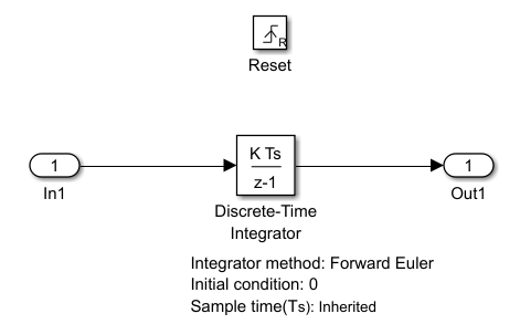
The subsystems contain identical Discrete-Time Integrator blocks, whose input is the Constant block at the root level of the model. The figure shows the contents of the resettable subsystem.

The figure shows the simulation output in the Scope block. You can observe the following in the scope:
control signalrepresents the control signal at the Enable port.When the control signal is 0, the enabled subsystem is disabled and the integrator does not change its output while the resettable subsystem continues to execute. The rising edge of the control signal triggers the reset port of the resettable subsystem and enables the enabled subsystem. Both subsystems reset their states at this time step.
The output from the enabled subsystem and the resettable subsystem are represented in the scope by
enabled outputandresettable outputsignal respectively. Notice that the enabled subsystem must be disabled for at least one time step before its states can be reset. The resettable subsystem does not have this limitation.

Model Examples
For model examples, see:
See Also
Enabled Subsystem | Enable | Resettable Subsystem | Reset | Integrator | Discrete-Time Integrator | Pulse Generator