Analyze Design in PID Tuner
To determine whether your PID controller meets your requirements, you can analyze the system response using the PID Tuner response plots.
Plot System Responses
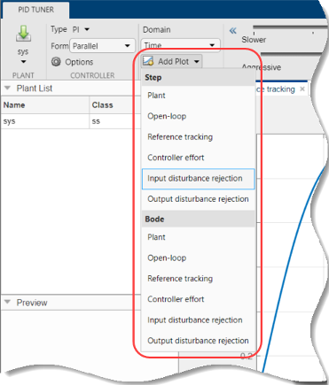
To determine whether the compensator design meets your requirements, you can analyze the system response using the response plots. On the PID Tuner tab, select a response plot from the Add Plot menu. The Add Plot menu also lets you choose from several step plots (time-domain response) or Bode plots (frequency-domain response).
For 1-DOF PID controller types such as PI, PIDF, and PDF, the software computes system responses based upon the following single-loop control architecture, where G is your specified plant and C is the PID controller:

For 2-DOF PID controller types such as PI2, PIDF2, and I-PD, the software computes responses based upon the following architecture:
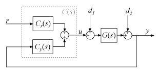
The system responses are based on the decomposition of the 2-DOF PID controller, C, into a setpoint component Cr and a feedback component Cy, as described in Two-Degree-of-Freedom PID Controllers.
The following table summarizes the available responses for analysis plots.
| Response | Plotted System (1-DOF) | Plotted System (2-DOF) | Description |
|---|---|---|---|
Plant | G | G | Plant response. Use to examine plant dynamics. |
Open-loop | GC | –GCy | Response of the open-loop controller-plant system. Use for frequency-domain design. Use when your design specifications include robustness criteria such as open-loop gain margin and phase margin. |
Reference tracking | (from r to y) | (from r to y) | Closed-loop system response to a step change in setpoint. Use when your design specifications include setpoint tracking. |
Controller effort | (from r to u) | (from r to u) | Closed-loop controller output response to a step change in setpoint. Use when your design is limited by practical constraints, such as controller saturation. |
Input disturbance rejection | (from d1 to y) | (from d1 to y) | Closed-loop system response to load disturbance (a step disturbance at the plant input). Use when your design specifications include input disturbance rejection. |
Output disturbance rejection | (from d2 to y) | (from d2 to y) | Closed-loop system response to a step disturbance at plant output. Use when you want to analyze sensitivity to modeling errors. |
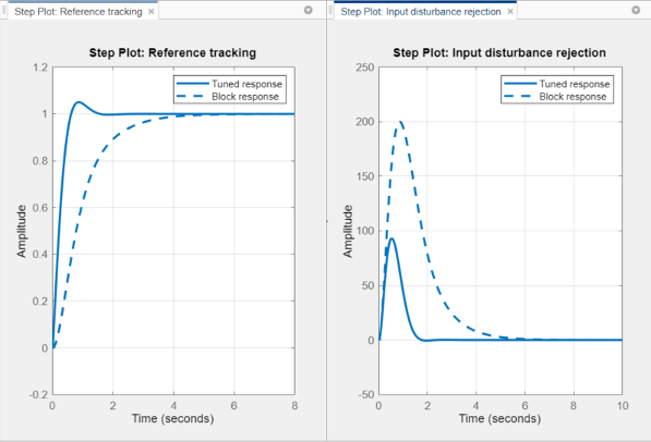
Compare Tuned Response to Block Response
By default, PID Tuner plots system responses using both:
The PID coefficient values in the controller block in the Simulink® model (Block response).
The PID coefficient values of the current PID Tuner design (Tuned response).
As you adjust the current PID Tuner design, such as by moving the sliders, the Tuned response plots change, while the Block response plots do not.
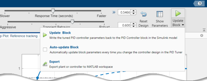
To write the current PID Tuner design to the Simulink model, click ![]() . When you do so, the current
Tuned response becomes the Block
response. Further adjustment of the current design
creates a new Tuned response line.
. When you do so, the current
Tuned response becomes the Block
response. Further adjustment of the current design
creates a new Tuned response line.
To hide the Block response, click ![]() Options, and clear Show Block
Response.
Options, and clear Show Block
Response.
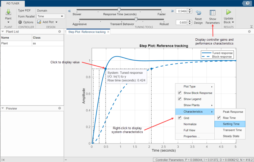
View Numeric Values of System Characteristics
You can view the values for system characteristics, such as peak response and gain margin, either:
Directly on the response plot — Use the right-click menu to add characteristics, which appear as blue markers. Then, left-click the marker to display the corresponding data panel.
In the Performance and robustness table — To display this table, click
 Show Parameters.
Export Plant or Controller to MATLAB Workspace
You can export the linearized plant model computed by PID Tuner to the MATLAB® workspace for further analysis. To do so, click Update Block and select Export.
In the Export dialog box, check the models that you want to export. Click
OK to export the plant or controller to the MATLAB workspace as state-space (ss) model object or
pid object, respectively.
Refine the Design
If the response of the initial controller design does not meet your requirements, you can interactively adjust the design. PID Tuner gives you two Domain options for refining the controller design:
Time(default) — Use the Response Time slider to make the closed-loop response of the control system faster or slower. Use the Transient Behavior slider to make the controller more aggressive at disturbance rejection or more robust against plant uncertainty.Frequency— Use the Bandwidth slider to make the closed-loop response of the control system faster or slower (the response time is 2/wc, where wc is the bandwidth). Use the Phase Margin slider to make the controller more aggressive at disturbance rejection or more robust against plant uncertainty.
In both modes, there is a tradeoff between reference tracking and disturbance rejection performance. For an example that shows how to use the sliders to adjust this tradeoff, see Tune PID Controller to Favor Reference Tracking or Disturbance Rejection.
Once you find a compensator design that meets your requirements, verify that it behaves in a similar way in the nonlinear Simulink model. For instructions, see Verify PID Design in Your Simulink Model.
Tip
To revert to the initial controller design after moving the sliders, click
![]() Reset Design.
Reset Design.