Create App Designer Instrument Panels by Using App Generator
You can create App Designer instrument panels to interface with real-time applications by using the App Generator button on the Real-Time tab in the Simulink® Editor. By using the App Generator, you can generate an instrument panel for selected signals and parameters in your model. You can open the generated app in App Designer to customize the instrument panel.
To create an instrument panel for your model by using the App Generator button:
Open the Simulink Real-Time™ model.
In the Simulink Editor, on the Real-Time tab, click Review Results > App Generator.
To create an instrument panel from the real-time application file MLDATX, select New > New, click No to remove the current session, and select the MLDATX file. For information about the difference between developing an instrument panel from a model SLX file or a real-time application MLDATX file, see the Tip About MLDATX and SLX Files.
In the App Generator, select Signals and Parameters in the model to add as components on the instrument panel. Click the Add to panel button.

After you add each signal or parameter, configure the Control Name and Control Type. The figure shows some App Generator selections for the
slrt_ex_oscmodel.
After configuring the Control Name and Control Type for the signals and parameters, click the Generate App button.
To customize the generated application, click the Open in App Designer button.
The App Generator adds controls to your instrument panel that enable the panel to interface with the real-time application. These controls include the target computer selector, connect button, load application button, start/stop button, stop time field, and system log. Any instrumented signals from the model are added in an axis component. For more information, see Create App Designer Instrument Panels by Using Simulink Real-Time Components.
Tip About MLDATX and SLX Files
You can develop an instrument panel app in the App Generator from a model SLX file (if you start the App Generator from the Real-Time tab in the Simulink Editor) or from a real-time application MLDATX file. It is recommended that you develop the instrument panel based on the MLDATX file, because—when developing from the MLDATX file—the App Generator only lists the signals and parameters that are present in the generated code. If you develop the instrument panel based on the SLX file, the App Generator can list more signals than are present in the generated code. These signals include virtual signals and signals to Scope blocks.
Open Real-Time Application and Create App
This example shows how to open a real-time application in the App Generator, add signals and parameters to an instrument panel app from the real-time application, and add signals and parameters to the instrument panel app from the model that corresponds to the real-time application..
Open the App Generator. In the MATLAB® Command Window, type:
slrtAppGenerator
To create a new instrument panel app, click the New button and select the real-time application file
slrt_ex_osc.mldatx. You created this file in Configure Instrument Panel Controls and Create App.Add signals and parameters to the instrument panel app. From the Signals and Parameters pane, select the
Amplitudeparameter, theFrequencyparameter, and theXfrFncsignal. Click the Add Selection button.To add signals and parameters from the model that corresponds to the real-time application, click the Add From Model button.
The App Generator opens the model and puts the model in bind mode for signal and parameter selection. For more information about bind mode, see Add Instruments to Real-Time Application by Using Simulink Editor.
To return to the App Generator, close bind mode in the model.
To create the instrument panel app, click the Generate App button.
Bind Parameter to Toggle or Radio Button Group
Because conversion functions are needed to transform the value of a
uibuttongroup 'SelectObject' property to a usable real-time parameter
value (and vice-versa), it is recommended that you use the App Generator to add button
groups for parameters. The App Generator adds the needed conversion code as part of the
instrument panel generation process.
Follow the steps in Open Real-Time Application and Create App, stopping before generating the instrument panel.
Select and add a parameter from the App Generator Signals and Parameters pane to the Bindings tab.
Select the parameter in the Bindings tab and change the Control Type to Button Group.
Configure the control in the Properties panel. The figure shows an example parameter setup from the
slrt_ex_oscmodel.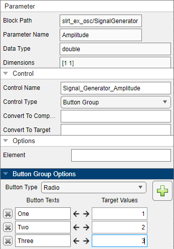
Generate the instrument panel and open it in App Designer.
The generated instrument panel has a button group to apply values to the parameter. To examine the generated conversion functions, open the Code View.
Add Callbacks for Target Computer Events
Callback functions add functionality to app controls. You can set up callback functions to execute based on real-time application events.
Follow the steps in Open Real-Time Application and Create App, stopping before generating the instrument panel.
Click the Target Events button.
Select the
Connectedevent from the list, click in the callback field, and add the function command:disp('Connected to target computer')Select the
Loadedevent from the list, click in the callback field, and add the function command:disp('Loaded MLDATX on target computer')To add these callbacks, click Apply. To close the Callback Editor dialog box, click OK.
Generate the instrument panel and open it in App Designer.
The generated instrument panel has callback code for the target computer events. To examine the generated conversion functions, open the Code View and see the added methods.
methods
    function ConnectedFcn(app, event)
        disp('Connected to target computer')
    end
    function LoadedFcn(app, event)
        disp('Loaded MLDATX on target computer')
    end
end
When you run the app and connect, your
ConnectedFcncallback executes automatically. When you load a real-time application, yourLoadedFcncallback executes automatically.
Select Multiple Controls and Edit Properties (Mass Edit)
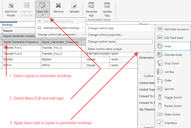
When you select multiple signals or parameters from the Bindings tab, you can use the Mass Edit button to edit the instrument binding configurations for the selected items. You can change the control type, change the control name, select whether to make the control name unique, and change tab placement of the control in the generated app.
Select multiple signal or parameter bindings for mass editing.
From the Mass Edit button, select the type of mass edit from the drop down menu. From this level you can Change control tab placement or select a mass edit type. The selection of mass edit type opens different editing methods, selecting:
Change control type opens the selection list of controls.
Change control properties opens the property inspector dialog box.
Change control name is an edit field for modifying the control names when the Control Type is Parameter Table or Signal Table.
Make control name unique adds a unique suffix to controls with identical names in a Parameter Table or Signal Table.
Apply the edit to the signal or parameter bindings en masse.
Create Multiple Tabs for App and Assign Controls (Layout)
Use the Layout button to open the Layout Options dialog box. From this dialog box, you can add or remove tabs in the generated app. Also, this dialog box lets you select grid usage for layout and choose whether the tabs open as windows in the generated app.
Click the Layout button.
To add a tab in the generated app, from the Layout Options dialog box, click the Add button. To remove a tab from the generated app, select an existing tab from the list and click the Remove button.
You can configure generation options for the tabs by selecting the Use the Use grid layout for each tab checkbox and the Open tabs as windows when app starts checkbox.
Close the dialog box when done.
See Also
Simulink Real-Time App
Generator | Instrument
Topics
- Add App Designer App to Inverted Pendulum Model
- Create and Update Instrument Panel for Stateflow Car Transmission
- Configure Target Computer Settings by Using Simulink Real-Time Explorer
- Real-Time Application and Target Computer Modes
- Configure and Control Real-Time Application by Using Simulink Real-Time Explorer
- Filter Hierarchical List of Signals and Parameters in Simulink Real-Time Explorer
- Stream Real-Time Signals by Using Simulink Real-Time Explorer
- Export and Import Signals in Instrument by Using Simulink Real-Time Explorer
- Tune Parameters by Using Simulink® Real-Time™ Explorer