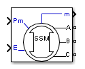
Simplified Synchronous Machine
(To be removed) Model the dynamics of simplified three-phase synchronous machine
The Specialized Power Systems library will be removed in R2026a. Use the Simscape™ Electrical™ blocks and functions instead. For more information on updating your models, see Upgrade Specialized Power System Models to use Simscape Electrical Blocks.
Libraries:
Simscape /
Electrical /
Electromechanical /
Synchronous
Description
The Simplified Synchronous Machine block models both the electrical and mechanical characteristics of a simple synchronous machine.
The electrical system for each phase consists of a voltage source in series with an RL impedance, which implements the internal impedance of the machine. The value of R can be zero but the value of L must be positive.
The Simplified Synchronous Machine block implements the mechanical system described by
where
| Δω = Speed variation with respect to speed of
operation H = constant of inertia Tm = mechanical torque Te = electromagnetic torque Kd = damping factor representing the effect of damper windings ω(t) = mechanical speed of the rotor ω0 = speed of operation (1 p.u.) | (1) |
Although the parameters can be entered in either SI units or per unit in the dialog box, the internal calculations are done in per unit. The following block diagram illustrates how the mechanical part of the model is implemented. The model computes a deviation with respect to the speed of operation; not the absolute speed itself.

The Kd damping coefficient simulates the effect of damper windings normally used in synchronous machines. When the machine is connected to an infinite network (zero impedance), the variation of machine power angle delta (δ) resulting from a change of mechanical power (Pm) can be approximated by the following second-order transfer function:
where
δ | Power angle delta: angle of internal voltage E with respect to terminal voltage, in radians |
Pm | Mechanical power in pu |
ωn | Frequency of electromechanical oscillations = in rad/s |
ζ | Damping ratio = |
ωs | Electrical frequency in rad/s |
Pmax | Maximum power in pu transmitted through reactance X at terminal voltage Vt and internal voltage E. Pmax = VtE/X, where Vt, E, and X are in pu |
H | Inertia constant(s) |
Kd | Damping factor (pu_of_torque / pu_of_speed) |
This approximate transfer function, which has been derived by assuming sin(δ) = δ, is valid for small power angles (δ < 30 degrees). It follows from the preceding ζ expression that the Kd value required to obtain a given ζ damping ratio:
Assumptions and Limitations
The electrical system of the Simplified Synchronous Machine block consists solely of a voltage source behind a synchronous reactance and resistance. All the other self- and magnetizing inductances of the armature, field, and damping windings are neglected. The effect of damper windings is approximated by the damping factor Kd. The three voltage sources and RL impedance branches are Y-connected (three wires or four wires). The load might or might not be balanced.
When you use Simplified Synchronous Machine blocks in discrete systems, you might have to use a small parasitic resistive load, connected at the machine terminals, to avoid numerical oscillations. Large sample times require larger loads. The minimum resistive load is proportional to the sample time. Remember that with a 25 μs time step on a 60 Hz system, the minimum load is approximately 2.5% of the machine nominal power. For example, a 200 MVA simplified synchronous machine in a power system discretized with a 50 μs sample time requires approximately 5% of resistive load or 10 MW. If the sample time is reduced to 20 μs, a resistive load of 4 MW should be sufficient.
Ports
Input
Output
Conserving
Parameters
In the Machines library you can choose between the SI units or the pu units Simplified Synchronous Machine blocks to specify the electrical and mechanical parameters of the model. These two blocks simulate exactly the same simplified synchronous machine model; the only difference is how you enter the parameter units.
To edit block parameters interactively, use the Property Inspector. From the Simulink® Toolstrip, on the Simulation tab, in the Prepare gallery, select Property Inspector.
Configuration
Specify the number of wires used in the three-phase Y connection: three-wire
(neutral not accessible) or four-wire (neutral is accessible). Default is
3-wire Y.
Select the mechanical power applied to the shaft or the rotor speed as a Simulink input of the block, or to represent the machine shaft by a Simscape rotational mechanical port.
Select Mechanical power Pm (default) to specify a
mechanical power input, in W or in pu, and change labeling of the block input to
Pm. The machine speed is determined by the machine Inertia J (or
inertia constant H for the pu machine) and by the difference between the mechanical
torque Tm, resulting from the applied mechanical power
Pm, and the internal electromagnetic torque
Te. The sign convention for the mechanical power is when the speed
is positive, a positive mechanical power signal indicates generator mode and a
negative signal indicates motor mode.
Select Speed w to specify a speed input, in rad/s or in
pu, and change labeling of the block input to w. The machine speed
is imposed and the mechanical part of the model (inertia constant H) is ignored. Using
the speed as the mechanical input allows modeling a mechanical coupling between two
machines.
The next figure indicates how to model a stiff shaft interconnection in a motor-generator set when friction torque is ignored in machine 2. The speed output of machine 1 (motor) is connected to the speed input of machine 2 (generator), while machine 2 electromagnetic torque output Te is applied to the mechanical torque input Tm of machine 1. The Kw factor takes into account speed units of both machines (pu or rad/s) and gear box ratio w2/w1. The KT factor takes into account torque units of both machines (pu or N.m) and machine ratings. Also, because the inertia J2 is ignored in machine 2, J2 referred to machine 1 speed must be added to machine 1 inertia J1.

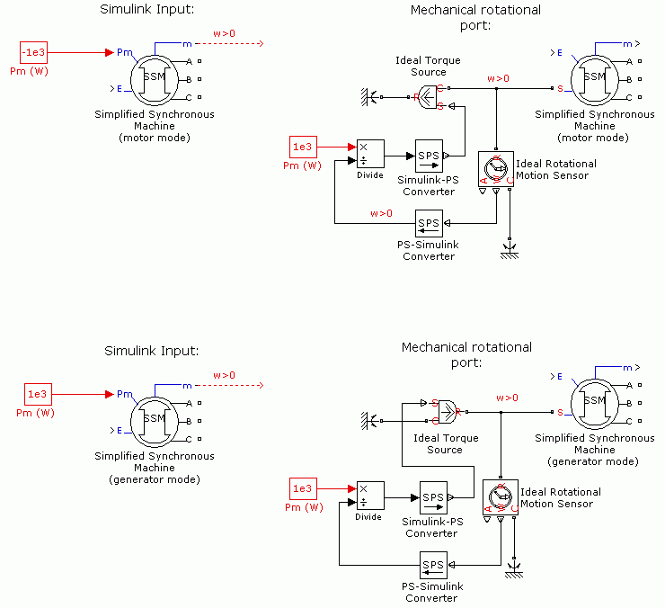
Select Mechanical rotational port to add to the block a
Simscape mechanical rotational port that allows connection of the machine shaft
with other Simscape blocks having mechanical rotational ports. The Simulink input representing the mechanical power Pm or the
speed w of the machine is then removed from the block.
The next figure indicates how to connect an Ideal Torque Source block from the Simscape library to the machine shaft to represent the machine in motor mode, or in generator mode, when the rotor speed is positive.
When this check box is selected, the measurement output uses the signal names to identify the bus labels. Select this option for applications that require bus signal labels to have only alphanumeric characters.
When this check box is cleared, the measurement output uses the signal definition to identify the bus labels. The labels contain nonalphanumeric characters that are incompatible with some Simulink applications.
Parameters
The nominal apparent power Pn (VA), frequency fn (Hz), and RMS line-to-line voltage Vn (V). Computes nominal torque and converts SI units to pu.
The inertia (J in kg.m2 or H in seconds) damping factor
(Kd) and number of pairs of poles (p). The damping factor must be specified in (pu of
torque)/(pu of speed) in both machine dialog boxes (in pu and in SI). Default is
[3.7 0 20] for pu and [3.895e6 0 20] for
SI.
The resistance R (Ω or pu) and reactance L (H or pu) for each phase. Default is
[0.02 0.3] for pu and [0.0204 0.8104e-3] for
SI.
The initial speed deviation (% of nominal), rotor angle (degrees), line current
magnitudes (A or pu), and phase angles (degrees). These values are automatically
computed by the load flow utility of the Powergui block. Default is [ 0,0
0,0,0 0,0,0 ].
Specifies the sample time used by the block. To inherit the sample time specified
in the Powergui block, set this parameter to −1. Default is
−1.
Advanced
To enable the Advanced tab, set the Simulation type parameter of the powergui block to Discrete and, on the Preferences tab, clear the Automatically handle discrete solver and Advanced tab solver settings of blocks parameter.
Specifies the integration method used by the block. The choices are
Trapezoidal non iterative(default),
Trapezoidal robust, and Backward Euler
robust.
When you select the Automatically handle discrete solver and Advanced
tab solver settings of blocks parameter in the powergui
block, the discrete solver model is automatically set to Trapezoidal
robust.
Trapezoidal non iterative requires you to add a
non-negligible shunt load at the machine terminals to maintain simulation stability,
and the simulation may fail to converge and stop when the number of machines increases
in the model.
Trapezoidal robust and Backward Euler
robust allow you to eliminate the need to use parasitic loads. To
eliminate the topological errors of the machines connected to an inductive circuit
(for example, a circuit breaker connected in series with the machine), the machine
models a negligible internal load of 0.01% of nominal power.
Trapezoidal robust is slightly more accurate than
Backward Euler robust, especially when the model is
simulated at larger sample times. Trapezoidal robust may
produce slight damped numerical oscillations on machine voltage in no-load conditions,
while Backward Euler robust prevents oscillations and
maintains accuracy.
Specifies the sample time used by the block. To inherit the sample time specified
in the Powergui block, set this parameter to −1. Default is
−1.
Load Flow
The load flow parameters define block parameters for use with the Load Flow tool of the Powergui block. These load flow parameters are for model initialization only. They have no impact on the block model or on the simulation performance.
The configuration of the Load Flow tab depends on the option selected for the Generator type parameter.
Specify the generator type of the voltage source.
Select swing to implement a generator controlling
magnitude and phase angle of its terminal voltage. The reference voltage magnitude and
angle are specified by the Swing bus or PV bus voltage and
Swing bus voltage angle parameters of the Load Flow Bus block
connected to the machine terminals.
Select PV (default) to implement a generator
controlling its output active power P and voltage magnitude V. P is specified by the
Active power generation P parameter of the block. V is
specified by the Swing bus or PV bus voltage parameter of the
Load Flow Bus block connected to the machine terminals. You can control the minimum
and maximum reactive power generated by the block by using the Minimum
reactive power Qmin and Maximum reactive power Qmax
parameters.
Select PQ to implement a generator controlling its
output active power P and reactive power Q. P and Q are specified by the
Active power generation P and Reactive power
generation Q parameters of the block, respectively.
Specify the active power that you want generated by the machine, in watts. When the machine operates in motor mode, you specify a negative value.
Dependencies
To enable this parameter, set Generator type to
PV or PQ.
Specify the reactive power that you want generated by the machine, in vars. A negative value indicates that the reactive power is absorbed by the machine.
Dependencies
To enable this parameter, set Generator type to
PQ.
Minimum reactive power that can be generated by the machine while keeping the
terminal voltage at its reference value. This reference voltage is specified in the
Swing bus or PV bus voltage parameter of the Load Flow Bus
block connected to the machine terminals. The default value is
-inf, which means that there is no lower limit on the reactive
power output.
Dependencies
To enable this parameter, set Generator type to
PV.
Maximum reactive power that can be generated by the machine while keeping the
terminal voltage at its reference value. This reference voltage is specified in the
Swing bus or PV bus voltage parameter of the Load Flow Bus
block connected to the machine terminals. The default value is inf,
which means that there is no upper limit on the reactive power output.
Dependencies
To enable this parameter, set Generator type to
PV.
Extended Capabilities
Version History
Introduced before R2006a