Average-Value Voltage Source Converter (Three-Phase)
Three-phase average-value bidirectional AC/DC voltage source converter

Libraries:
Simscape /
Electrical /
Semiconductors & Converters /
Converters
Description
The Average-Value Voltage Source Converter (Three-Phase) block converts electrical energy from AC to DC voltage or from DC to AC voltage according to an input three-phase modulation wave. You can specify the modulation wave directly or through phasor quantities such as the magnitude and phase shift. The corresponding input power is equal to the sum of the fixed power loss and the output power.
This block can work in both time and frequency-and-time simulation modes. If you set the
AC frequency parameter to Variable,
this block works only in time simulation mode. If you select
Constant, this block works in both time and
frequency-time simulation modes. For more information, see Frequency and Time Simulation Mode.
Enable or Disable Converter
Since R2026a
You can enable or disable the functionality of the Average-Value Voltage Source Converter (Three-Phase) block by selecting the Expose port to enable or disable converter parameter and applying a signal to the physical signal port ENA.
For a grid-connected voltage source converter, if you disable the converter by applying a
signal of value 0 to the ENA port, the
Average-Value Voltage Source Converter
(Three-Phase) block operates as an average-value diode-based
rectifier. If you enable the converter by applying a signal of value
1 to the ENA port, the block operates as a
normal converter.
This figure shows the operation switching between the diode-based rectification and normal converter operation depending on the value at the ENA port.

For a grid-connected application, if you disable the converter, the modeling equations are:
where:
va, vb, and vc are the respective AC phase voltages.
ia, ib, and ic are the respective AC phase currents that flow in the converter.
Vrms is the RMS AC line-line voltage.
Vdc is the DC-side voltage.
Idc is the DC-side current that flows in the converter.
Pdc is the DC-side power output.
Pac is the power that flows in the AC side of the converter.
Irms is the RMS phase current.
i0 is the zero-sequency current at the AC side of the converter.
Rac is the equivalent per-phase series resistance at the AC side of the converter.
If you enable the converter, the modeling equations are:
where:
va, vb, and vc are the respective AC phase voltages.
ia, ib, and ic are the respective AC phase currents that flow in the converter.
Vdc is the DC-side voltage.
Idc is the DC-side current that flows in the converter.
Pdc is the DC-side power output.
Pac is the power that flows in the AC side of the converter.
Ploss is the total power loss of the converter.
ModWave(1), ModWave(2), and ModWave(3) are the first, second, and third element of the vector at the ModWave input port, respectively.
Losses Parameterization
Switching losses, conduction losses, and quiescent losses are the main heat sources for a converter.
The switching losses are defined by this equation:
where:
ks is the proportionality constant that depends on the turn-on and turn-off intervals and switching frequency. Specify this value by setting the Switching losses coefficient, ks parameter.
vdc is the dc-link voltage.
is the root mean square (RMS) phase current, where
The conduction losses are defined by this equation:
where:
kc1 is the coefficient of the conduction losses that depends on the on-state zero current collector-emitter voltage of the transistor and on the forward voltage drop of the diode. Specify this value by setting the Conduction losses coefficient, kc1 parameter.
kc2 is the coefficient of the conduction losses that depends on the state resistance of the transistor and on the anti-parallel diode. Specify this value by setting the Conduction losses coefficient, kc2 parameter.
If you disable the converter, the converter works as an average-value diode-based rectifier. In this scenario, the switching losses are negligible and the conduction losses are defined by this equation:
where krec is the value of the Rectifier conduction losses coefficient, krec parameter. (since R2026a)
The quiescent losses are defined by the Fixed power loss parameter, Pfixed.
The sum of the switching, conduction, and quiescent losses define the total power losses of the converter:
If not available, you can also obtain the
ks,
kc1,
kc2 and
Pfixed parameters values from the
power losses profile, by setting the Losses parameterization
parameter to Profile: loss=f(Irms,vdc_nom). The block
then solves this equation and calculates the values of the parameters:
where is the vector of power loss values, Converter losses, corresponding to the RMS current for converter losses parameter, , and the Nominal dc-link voltage, vdc_nom.
Model Thermal Effects
This block has one optional thermal port. To control the visibility of the thermal port, set the Modeling option parameter to either:
No thermal port— The block does not contain a thermal port.Show thermal port— The block contains one thermal conserving port.
Variables
To set the priority and initial target values for the block variables before simulation, use the Initial Targets section in the block dialog box or Property Inspector. For more information, see Set Priority and Initial Target for Block Variables.
Nominal values provide a way to specify the expected magnitude of a variable in a model. Using system scaling based on nominal values increases the simulation robustness. You can specify nominal values using different sources, including the Nominal Values section in the block dialog box or Property Inspector. For more information, see System Scaling by Nominal Values.
Examples

Asynchronous Machine Direct Torque Control with Space Vector Modulator
Control an asynchronous machine (ASM) using the direct-torque control method with space vector modulator. A PI-based speed controller supplies the torque reference. The direct-torque controller generates the reference voltages required by the space vector modulator. A DC voltage source feeds the ASM through a controlled average-value voltage source converter.

Microgrid with Electric Vehicles V2G (Vehicle-to-Grid) Support
Model a microgrid and how to regulate its frequency by using vehicle-to-grid (V2G) support from electric vehicles (EVs).
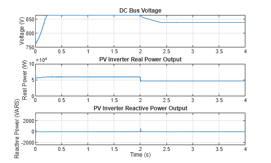
Control Three-Phase Solar Inverter
Control a three-phase single-stage solar photovoltaic (PV) inverter using a Solar PV Controller (Three-Phase) block. In a grid-connected PV plant, a PV controller extracts the maximum power from the solar array and feeds it to the grid. To extract the maximum available PV power, the controller uses a maximum power point tracking (MPPT) algorithm.

Model Static Synchronous Compensator Using Voltage Source Converter
Models a hybrid var compensator that includes a static synchronous compensator (STATCOM) and a thyristor-switched capacitor (TSC).
Ports
Input
Conserving
Parameters
References
[1] M. N., Rajput. "Thermal modeling of permanent magnet synchronous motor and inverter." Master's Thesis, Georgia Institute of Technology, 2016. https://hdl.handle.net/1853/55053.