Control Function-Call Subsystems by Using bind Actions
You can bind specified data and events to a state by using bind
actions. Events bound to a state can be broadcast only by the actions in that state or its
children. You can also bind a function-call event to a state to enable or disable the
function-call subsystem that the event triggers. The function-call subsystem enables when the
state with the bound event is entered and disables when that state is exited. Execution of the
function-call subsystem is fully bound to the activity of the state that calls it.
Bind a Function-Call Subsystem to a State
By default, a function-call subsystem is controlled by the chart in which the associated
function call output event is defined. This association means that the function-call
subsystem is enabled when the chart wakes up and remains active until the chart goes to
sleep. To achieve a finer level of control, you can bind a function-call subsystem to a
state within the chart hierarchy by using a bind action (see Bind Actions).
You can bind function-call output events to a state. When you create this type of binding, the function-call subsystem that is called by the event is also bound to the state. In this situation, the function-call subsystem is enabled when the state is entered and disabled when the state is exited.
When you bind a function-call subsystem to a state, you can fine-tune the behavior of the subsystem when it is enabled and disabled, as described in the following sections:
Handle Outputs When the Subsystem is Disabled
Although function-call subsystems do not execute while disabled, their output signals are available to other blocks in the model. If a function-call subsystem is bound to a state, you can hold its outputs at their values from the previous time step or reset the outputs to their initial values when the subsystem is disabled. Follow these steps:
Double-click the Outport block of the subsystem to open the Block Parameters dialog box.
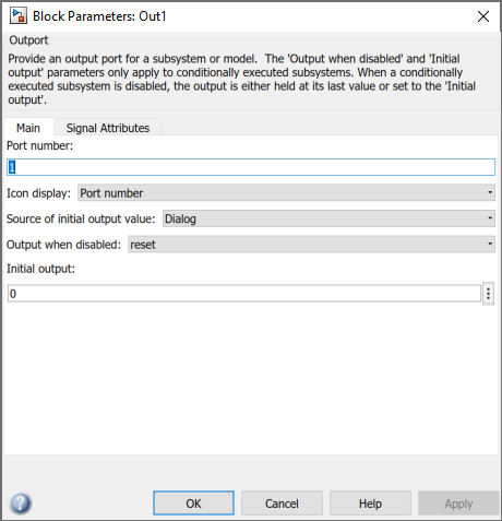
Select an option for Output when disabled:
Select: To: heldMaintain most recent output value resetReset output to its initial value Click OK to record the settings.
Note
Setting Output when disabled is meaningful only when the function-call subsystem is bound to a state, as described in Bind a Function-Call Subsystem to a State.
Control Behavior of States When the Subsystem is Enabled
If a function-call subsystem is bound to a state, you can hold the subsystem state variables at their values from the previous time step or reset the state variables to their initial conditions when the subsystem executes. In this way, the binding state gains full control of state variables for the function-call subsystem. Follow these steps:
Double-click the trigger port of the subsystem to open the Block Parameters dialog box.
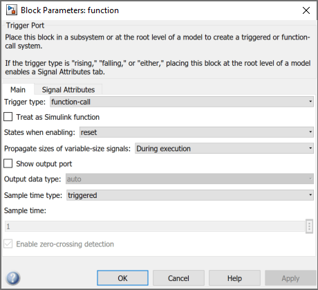
Select an option for States when enabling:
Select: To: heldMaintain most recent values of the states of the subsystem that contains the trigger port resetRevert to the initial conditions of the states of the subsystem that contains this trigger port inheritInherit this setting from the parent subsystem of the function call initiator. If the parent of the initiator is the model root, the inherited setting is held. If the trigger has multiple initiators, the parents of all initiators must have the same setting: either all
heldor allreset.Click OK to record the settings.
Note
Setting States when enabling is meaningful only when the function-call subsystem is bound to a state, as described in Bind a Function-Call Subsystem to a State.
Bind Function-Call Subsystem to State
This model triggers a function-call subsystem with a trigger event E that binds to a state of a chart. The model uses a fixed-step solver with a fixed-step size of 1.
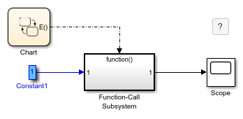
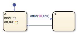
The chart contains two states. Event E binds to state A with the action
bind:E
Event E is defined for the chart with a scope of Output to Simulink and a trigger type of function-call.
The function-call subsystem contains a trigger port block, an input port, an output port, and a simple block diagram. The block diagram increments a counter by 1 at each time step, using a Unit Delay block.
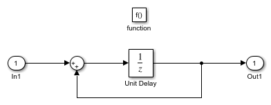
The Block Parameters dialog box for the trigger port contains these settings:
Trigger type:
function-call.States when enabling:
reset. This setting resets the state values for the function-call subsystem to zero when it is enabled.Sample time type:
triggered. This setting sets the function-call subsystem to execute only when it is triggered by a calling event while it is enabled.
Setting Sample time type to periodic enables the Sample time field below it, which defaults to 1. These settings force the function-call subsystem to execute for each time step specified in the Sample time field while it is enabled. To accomplish this, the state that binds the calling event for the function-call subsystem must send an event for the time step coinciding with the specified sampling rate in the Sample time field. States can send events with entry or during actions at the simulation sample rate.
For fixed-step sampling, the Sample time value must be an integer multiple of the fixed-step size.
For variable-step sampling, the Sample time value has no limitations.
To see how a state controls a bound function-call subsystem, begin simulating the model.
At time t = 0, the default transition to state
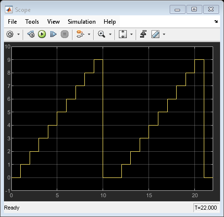
Aoccurs. StateAexecutes its bind and entry actions. The binding action binds eventEto stateA, enabling the function-call subsystem and resetting its state variables to 0. The entry action triggers the function-call subsystem and executes its block diagram. The block diagram increments a counter by 1 using a Unit Delay block. The Unit Delay block outputs a value of 0 and holds the new value of 1 until the next call to the subsystem.At time t = 1, the next update event from the model tests state
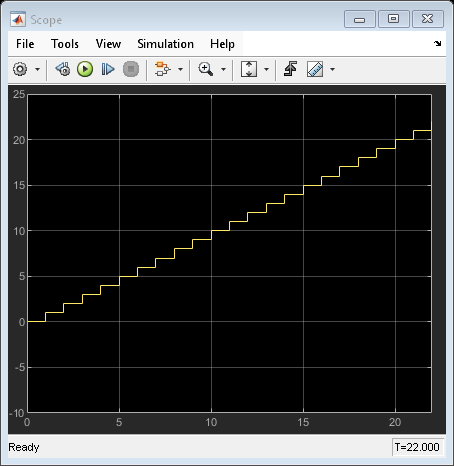
Afor an outgoing transition. The transition to stateBdoes not occur because the temporal operatorafter(10,tick)allows the transition to be taken only after ten update events are received. StateAremains active and its during action triggers the function-call subsystem. The Unit Delay block outputs its held value of 1. The subsystem also increments its counter to produce the value of 2, which the Unit Delay block holds until the next triggered execution.The next eight update events increment the subsystem output by one at each time step.
At time t = 10, the transition from state
Ato stateBoccurs. Because the binding to stateAis no longer active, the function-call subsystem is disabled, and its output drops back to 0.At time t = 11, the transition from state
Bto stateAoccurs. Again, the binding action enables the function-call subsystem. Subsequent update events increment the subsystem output by one at each time step until the next transition to stateBoccurs at time t = 21.
Avoid Muxed Trigger Events with Binding
Binding events gives control of a function-call subsystem to a single state in a chart. This control does not work when you allow other events to trigger the function-call subsystem through a mux. For example, this model defines two function-call events to trigger a function-call subsystem using a Mux block.
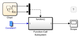
In the chart, E1 binds to state A, but E2 does not. State B sends the triggering event E2 in its entry action.
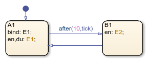
When you simulate this model, the output does not reset when the transition from state A to state B occurs.
Binding is not recommended when you provide multiple trigger events to a function-call subsystem through a mux. Muxed trigger events can interfere with event binding and cause undefined behavior.