Validate Component Behaviors Using Architecture Test Harnesses
R2026bBefore integrating software component models into a larger software composition, you can validate configured communication and execution behaviors in isolation using an architecture test harness. For more information about configuring these behaviors, see Configure Communication and Execution Behavior of Software Components.
A test harness creates a controlled environment by replacing external interactions with mock components that emulate senders, receivers, clients, and servers. Because test harnesses are generated as software architecture models, the simulation enforces configured quality of service (QoS) properties — verifying not only functional behavior, but also service interactions and execution timing.
Note
This workflow requires the Software Component Designer for Simulink® support package, which provides the authoring and simulation capabilities for software component models. For installation instructions, see Install Software Component Designer for Simulink Support Package.
Create an Architecture Test Harness Model
You can create and manage architecture test harnesses from the Software Component tab, which provides actions to add, open, and run test harnesses for software components.
To create a test harness:
Open the software component model that you want to validate.
On the Software Component tab, in the Component Test Harness section, click Add Test Harness .
In the Create Test Harness dialog box, specify the harness name and file path.
Click OK.
The system generates a software architecture model that contains the component under test and mock components for its connected ports. Depending on the ports defined on the component, the generated harness includes:
A mock senders model if the component has input or client ports.
A mock receivers model if the component has output or server ports.
The architecture test harness references the same data dictionary as the component under test. Interface definitions are shared, not duplicated. The test harness reflects changes to interfaces in the dictionary, keeping both models in sync.
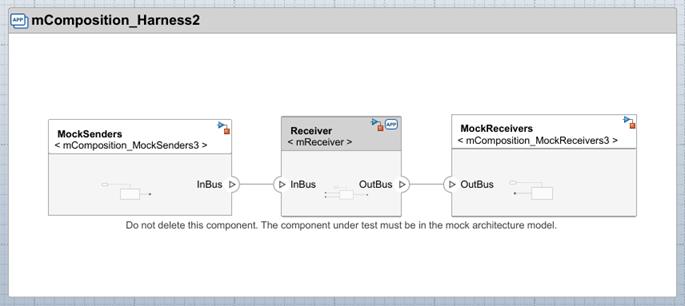
Implement Behavior of Mock Components
Mock components represent external components that interact with the component under test. You can use them to control inputs, simulate service interactions, and observe communication behavior without requiring the full system to be ready.
Mock senders represent components that provide data or invoke services required by the component under test.
Mock receivers represent components that receive data or provide services requested by the component under test.
Each mock component is implemented as a referenced Simulink model. To define behavior of a mock component, double-click the mock component on the canvas and edit the referenced model.
Typical mock component patterns include:
Mock senders that use Constant, Signal Builder, or From Workspace blocks to provide test data at defined intervals.
Mock receivers that use Terminator or To Workspace blocks to capture output data for post-simulation analysis.
Mock servers that use Simulink Function blocks with simple return logic (constant values or lookup tables) to emulate service responses.
Simulate Components with Test Harnesses
After you create an architecture test harness and configure mock components, simulate the test harness to validate the run-time behavior of the component under test.
You can simulate an architecture test harness directly from the Software Component tab or from the harness model itself.
To simulate from the original component model, on the Software Component tab, click Run with Test Harness .
To simulate from the harness model, open the test harness and click Run .
Use standard Simulink and architecture modeling tools to observe and analyze behavior during simulation:
Monitor logged signals and states using the Simulation Data Inspector.
Observe data flow and service interactions between the component under test and mock components.
Verify execution order and timing based on the configured communication and execution behaviors.
You can log input and output signals to capture results and compare expected and actual behavior.
You can change the execution order and sample time of component functions in the architecture test harness using the Functions Editor.
See Also
Functions Editor | Interface Editor

