Simulate UAV Mission in Urban Environment
This example shows how to create and simulate a UAV mission in an urban environment in MATLAB® and Simulink® using the uavMission and uavScenario objects, as well as OpenStreetMap® (OSM) data from Manhattan, New York. In this example, you import a plan file created in the QGroundControl app.


Create UAV Scenario with Mission
In this example, you create a scene based on New York City and add a quadrotor UAV to the scenario to execute a flight mission. You can use UAV missions to design flight trajectories that command a UAV to fly over and orbit buildings in the city.
Create a UAV scenario with the reference location set to 1 Wall Street at [40.707088 -74.012146 0].
scene = uavScenario(ReferenceLocation=[40.707088 -74.012146 0],UpdateRate=5);
Set the x-, and y-limits and colors for the terrain and building data. Import the terrain elevation data and the OSM building data by using the addMesh object function.
xTerrainLimits = [-200 200];
yTerrainLimits = [-200 200];
color = [0.6 0.6 0.6];
addMesh(scene,"terrain",{"gmted2010",xTerrainLimits,yTerrainLimits},color)
xBuildingLimits = [-150 150];
yBuildingLimits = [-150 150];
color = [0.6431 0.8706 0.6275];
addMesh(scene,"buildings",{"manhattan.osm",xBuildingLimits,yBuildingLimits,"auto"},color)
Since the UAV must fly around an urban environment containing many obstacles, such as tall buildings, define the UAV as a quadrotor, as quadrotors are more than fixed-wing UAVs. Add a quadrotor to the scenario as a uavPlatform object at the default location. Add a mesh to the quadrotor, and rotate the mesh by pi on its z-axis so that it is oriented with the quadrotor model.
plat = uavPlatform("UAV",scene);
updateMesh(plat,"quadrotor",{3},[1 0 0],eul2tform([0 0 pi]));
Import and visualize the orbitexample.plan mission file, which contains waypoints between the buildings along Broadway Street and Wall Street. For more details on how to create a mission manually, see the uavMission object.
m = uavMission(PlanFile="orbitexample.plan");
figure
show3D(scene);
hold on
ax = show(m, ReferenceLocation=scene.ReferenceLocation);
missionLine = findobj(ax,"type","line");
missionText = findobj(ax,"type","text");
for idx = 1:numel(missionLine)
    missionLine(idx).LineWidth = 2;
end
for idx = 1:numel(missionText)
    p = missionText(idx).Position;
    missionText(idx).Position = p+[0 10 0];
    missionText(idx).HorizontalAlignment = "center";
    missionText(idx).VerticalAlignment = "bottom";
    missionText(idx).Margin = 1;
    missionText(idx).BackgroundColor = [1 1 1];
end
view([0 90])
hold off

Simulate Mission in MATLAB
Now that the scenario and mission are ready, you can use the multirotorMissionParser or fixedwingMissionParser object to parse the mission and generate trajectories for different types of UAVs. Since you are using a quadrotor, use multirotorMissionParser to create the flight trajectory.
parser = multirotorMissionParser;
traj = parse(parser,m,scene.ReferenceLocation);
Visualize the generated multirotor trajectory on the mission scene.
figure
ax = show3D(scene);
light(ax,Position=[-800 -800 800])
view([10 30])
hold on
show(m,ReferenceLocation=scene.ReferenceLocation);
missionLine = findobj(ax,"type","line","tag","PathLine");
missionLine.LineWidth = 2;
missionText = findobj(ax,"type","text");
for idx = 1:numel(missionText)
    p = missionText(idx).Position;
    missionText(idx).Position = p+[0 10 0];
    missionText(idx).HorizontalAlignment = "center";
    missionText(idx).VerticalAlignment = "bottom";
    missionText(idx).FontWeight = "bold";
end
show(traj,NumSamples=200);

Create a scenario simulation loop that uses the move object function to move the UAV platform according to the output of the trajectory query and the camtarget function to track the UAV during simulation.
camzoom(ax,20)
setup(scene)
while scene.CurrentTime <= traj.EndTime
    motion = query(traj,scene.CurrentTime);
    move(plat,motion);
    show3D(scene,Parent=ax,FastUpdate=true);
    nedPos = motion(1:3);
    camtarget(ax,[nedPos(2) nedPos(1) -nedPos(3)]);
    advance(scene);
    drawnow limitrate
end
hold off

Simulate Mission in Simulink
Now simulate the multirotor mission in Simulink using the mSimulateMultirotorMission model. Open the model.
open_system("mSimulateMultirotorMission.slx")The model contains a MATLAB Function block that generates the multirotor trajectory and then drives the quadrotor using the UAV Scenario Motion Write block.
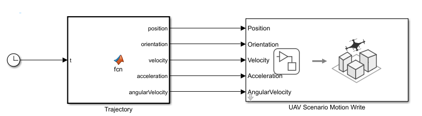
The model takes the trajectory information as parameters from the MATLAB workspace and then generates a motion vector based on the sample time. Open the MATLAB Function block Trajectory.
open_system("mSimulateMultirotorMission/Trajectory")Extract the trajectory specifications from the reference trajectory object traj into the MATLAB workspace to map them into MATLAB Function block, and then simulate the model to watch the quadrotor follow the mission.
wpts = traj.Waypoints;
vels = traj.Velocities;
accs = traj.Accelerations;
jerks = traj.Jerks;
snaps = traj.Snaps;
yaws = traj.Yaws;
toas = traj.TimeOfArrival;
sim("mSimulateMultirotorMission");