Memoryless Nonlinearity
Apply amplifier models to complex baseband signal
Libraries:
Communications Toolbox /
RF Impairments and Components
Description
The Memoryless Nonlinearity block applies amplifier models to a complex baseband signal. Use this block to model memoryless nonlinear impairments caused by signal amplification in the radio frequency (RF) transmitter or receiver. For more information, see Amplifier Model Methods.
Examples
Add Saleh Model of Power Amplifier to 16-QAM Signal in Simulink
This example applies the Saleh method of memoryless nonlinearity to a 16-QAM modulated signal. To show the Saleh model of a power amplifier, the example applies exaggerated levels that are not typical for modern radios.
In this example, the cm_mnl_saleh_16qam
model 16-QAM modulates a signal containing a complete set of constellation points and passes them to Memoryless Nonlinearity blocks configured to apply the Saleh method with the default AM/AM and AM/PM distortion settings, AM/AM distortion alone, and AM/PM distortion alone. The model includes Constellation Diagram blocks after each Memoryless Nonlinearity block so you can analyze the impact of each impairment on the constellation.
In the model, you can click the Plot Transfer Curve Callback Button (Simulink) block to run the testPA.m
helper function. The testPA
helper function plots this amplifier transfer curve for the Saleh method in its default configuration to show the nonlinear input-to-output signal. After amplification, plotted constellation points get displaced according to the input-to-output characteristics of the amplifier model. The voltage for each constellation point determines the direction and magnitude of distortion for each point in the constellation.
This set of constellation diagrams shows the constellation distortion for the amplifier configured to distort the amplitude and phase individually and together.
The
AMAM
diagram shows the signal with amplitude-to-amplitude distortion but no amplitude-to-phase distortion. AM/AM distortion displaces constellation points radially away from or toward the origin. For the Saleh method and specified operating characteristics, the inner corner constellation points move away from the origin and the outer corner constellation points move toward the origin. The noncorner constellation points move a negligible amount.The
AMPM
diagram shows the signal with amplitude-to-phase distortion but no amplitude-to-amplitude distortion. AM/PM distortion causes rotation of constellation points. Constellation points farther from the origin are more displaced than points closer to the origin.The
AMAM and AMPM
diagram shows the signal with amplitude-to-amplitude distortion and amplitude-to-phase distortion. In this diagram, the constellation points move away from or toward the origin and rotate counter-clockwise.
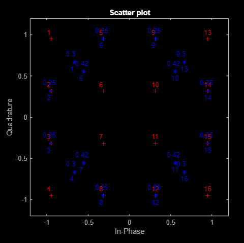
This scatter plot of the constellation points shows points displaced by AM/AM distortion only. The scatterplot
function used here plots constellation point locations labeled to highlight the relative distance each point has moved from the ideal constellation point location. To analyze the magnitude and direction each constellation point moved, you would need to replot the input and output characteristic curve for the current operating characteristics.
To explore the model try adjusting settings for the Memoryless Nonlinearity blocks to:
Apply different impairment model methods.
Apply different levels of impairments.
Update the
testPA.m
helper function to plot and analyze input and output characteristics at nondefault Memoryless Nonlinearity block settings.
Add RF Impairments to DQPSK Signal
This example applies RF impairments to a signal modulated by the differential quadrature phase shift keying (DQPSK) method. To show the RF impairments, the example applies exaggerated levels that are not typical levels for modern radios.
In this example, the slex_rcvrimpairments_dqpsk
model DQPSK-modulates a random signal and applies various RF impairments to the signal. The model uses impairment blocks from the RF Impairments library. The InitFun
callback function initializes simulation variables. For more information, see Model Callbacks (Simulink).
After the impairment blocks, the signal forks into two paths. One path applies DC blocking, automatic gain control (AGC), and I/Q imbalance compensation to the signal before demodulation. The signal on the correction path is adjusted by the DC Blocker, AGC, and I/Q Imbalance Compensator blocks. Because the signal is DQPSK modulated, no carrier synchronization is required. The second path goes directly to demodulation. After demodulation, an error rate calculation is performed on both signals. The model includes Constellation Diagram blocks after modulation, before correction, and after correction so that you can analyze the constellation.
When the model runs, constellation diagrams plot the signal at these stages in the simulation:
The
After Modulation
constellation diagram shows the reference DQPSK-modulated signal constellation.The
Before Correction
constellation diagram shows the attenuated and distorted signal constellation.The
After Correction
constellation diagram shows the signal has been amplified and improved after the correction blocks.
The error rate for the demodulated signal without AGC is primarily caused by free space path loss and I/Q imbalance. The QPSK modulation minimizes the effects of the other impairments.
Error rate for corrected signal: 0.000 Error rate for uncorrected signal: 0.042
To explore the model try:
Adjusting RF impairment settings, rerun the model, and notice the changes to the constellation diagrams and error rates.
Modifying the model to add an equalizer stage before the demodulation. Equalization has inherent ability to reduce some of the distortion caused by impairments. For more information, see Equalization.
Ports
Input
In1 — Input RF baseband signal
scalar | column vector
Input RF baseband signal, specified as a scalar or column vector.
Data Types: double
| single
Complex Number Support: Yes
Output
Out1 — Output RF baseband signal
scalar | column vector
Output RF baseband signal, returned as a scalar or column vector. The output is of the same data type as the input.
Parameters
To edit block parameters interactively, use the Property Inspector. From the Simulink® Toolstrip, on the Simulation tab, in the Prepare gallery, select Property Inspector.
Main Tab
Model — Amplifier nonlinearity model
Cubic polynomial
(default) | AM/AM - AM/PM
| Modified Rapp
| Saleh
Specify the amplifier nonlinearity model as one of the following methods:
Cubic polynomial
AM/AM - AM/PM
Modified Rapp
Saleh
For more information, see Amplifier Model Methods.
Linear power gain (dB) — Linear gain of amplifier
0
(default) | real scalar
Linear gain, specified as a scalar in dB.
Dependencies
To enable this parameter, set Model to Cubic
polynomial
or Modified
Rapp
.
Type of Non-linearity — Third-order nonlinearity type
IIP3
(default) | OIP3
| IP1dB
| OP1dB
| IPsat
| OPsat
Third-order nonlinearity type in dBm, specified as one of these options:
IIP3
— Input third-order intercept pointOIP3
— Output third-order intercept pointIP1dB
— Input 1 dB compression pointOP1dB
— Output 1 dB compression pointIPsat
— Input saturation pointOPsat
— Output saturation point
Dependencies
To enable this parameter, set Model to Cubic
polynomial
.
IIP3 (dBm) — Input third-order intercept point
Inf
(default) | real positive number
Input third-order intercept point, specified as a real positive number in dBm.
Dependencies
To enable this parameter, set Model to Cubic
polynomial
and Type of Non-Linearity to
IIP3
.
OIP3 (dBm) — Output third-order intercept point
Inf
(default) | real positive number
Output third-order intercept point, specified as a real positive number in dBm.
Dependencies
To enable this parameter, set Model to Cubic
polynomial
and Type of Non-Linearity to
OIP3
.
IP1dB (dBm) — Input 1 dB compression point
Inf
(default) | real positive number
Input 1 dB compression point, specified as a real positive number in dBm.
Dependencies
To enable this parameter, set Model to Cubic
polynomial
and Type of Non-Linearity to
IP1dB
.
OP1dB (dBm) — Output 1 dB compression point
Inf
(default) | real positive number
Output 1 dB compression point, specified as a real positive number in dBm.
Dependencies
To enable this parameter, set Model to Cubic
polynomial
and Type of Non-Linearity to
OP1dB
.
IPsat (dBm) — Input saturation point
Inf
(default) | real positive number
Input saturation point, specified as a real positive number in dBm.
Dependencies
To enable this parameter, set Model to Cubic
polynomial
and Type of Non-Linearity to
IPsat
.
OPsat (dBm) — Output saturation point
Inf
(default) | real positive number
Output saturation point, specified as a positive real number in dBm.
Dependencies
To enable this parameter, set Model to Cubic
polynomial
and Type of Non-Linearity to
OPsat
.
Lookup table (Pin(dBm), Pout(dBm), deg) — Lookup table
[ -25, 5, -1; -10, 20, -2; 0, 27, 5; 5, 28,
12 ]
(default) | M-by-3 real matrix
Table lookup entries specified as a real M-by-3 matrix. This table expresses the model output power dBm level in matrix column 2 and the model phase change in degrees in matrix column 3 as related to the absolute value of the input signal power of matrix column 1 for the AM/AM-AM/PM model method. The column 1 input power must increase monotonically.
Dependencies
To enable this parameter, set Model to AM/AM -
AM/PM
.
Output saturation level (V) — Output saturation level
1
(default) | real positive number
Voltage output saturation level, specified as a real positive number in dBm.
Dependencies
To enable this parameter, set Model to Modified
Rapp
.
Magnitude smoothness factor — Magnitude smoothness factor
2
(default) | real positive number
Magnitude smoothness factor for the AM/AM calculations of the modified Rapp model method, specified as a positive real number.
Dependencies
To enable this parameter, set Model to Modified
Rapp
.
Phase gain (rad) — Phase gain
-0.45
(default) | real scalar
Phase gain for the AM/PM calculations of the modified Rapp model method, specified as a real scalar in radians.
Dependencies
To enable this parameter, set Model to Modified
Rapp
.
Phase saturation — Phase saturation
0.88
(default) | real positive number
Phase saturation for the AM/PM calculations of the modified Rapp model method, specified as a positive real number.
Dependencies
To enable this parameter, set Model to Modified
Rapp
.
Phase smoothness factor — Phase smoothness factor
3.43
(default) | real positive number
Phase smoothness factor for the AM/PM calculations of the modified Rapp model method, specified as a positive real number.
Dependencies
To enable this parameter, set Model to Modified
Rapp
.
Input scaling (dB) — Scaling factor for input signal level
0
(default) | nonnegative real number
Scaling factor for input signal level for the Saleh model method, specified as a nonnegative real number in dB.
Dependencies
To enable this parameter, set Model to Saleh
.
AM / AM parameters [alpha beta] — AM/AM conversion parameters
[ 2.1587, 1.1517 ]
(default) | two-element vector
AM/AM two-tuple conversion parameters for the Saleh model method, specified as a two-element vector of nonnegative real numbers.
Dependencies
To enable this parameter, set Model to Saleh
.
AM / PM parameters [alpha beta] — AM/PM conversion parameters
[ 4.0033, 9.1040 ]
(default) | two-element vector
AM/PM two-tuple conversion parameters for the Saleh model mehtod, specified as a two-element vector of nonnegative real numbers.
Dependencies
To enable this parameter, set Model to Saleh
.
Output scaling (dB) — Scaling factor for output signal level
0
(default) | nonnegative real number
Scaling factor for output signal level for the Saleh model method, specified as nonnegative real number in dB.
Dependencies
To enable this parameter, set Model to Saleh
.
Reference load (ohm) — Reference load
1
(default) | positive scalar
Reference load value in ohms, specified as a positive scalar. Use this value to convert between the voltage levels and the signal and noise power levels.
Tunable: Yes
Simulate using — Type of simulation to run
Code generation
(default) | Interpreted execution
Type of simulation to run, specified as Code generation
or
Interpreted execution
.
Code generation
— Simulate the model by using generated C code. The first time you run a simulation, Simulink generates C code for the block. The model reuses the C code for subsequent simulations unless the model changes. This option requires additional startup time, but the speed of the subsequent simulations is faster than with theInterpreted execution
option.Interpreted execution
— Simulate the model by using the MATLAB® interpreter. This option shortens startup time, but the speed of subsequent simulations is slower than with theCode generation
option. In this mode, you can debug the source code of the block.
Block Characteristics
Data Types |
|
Multidimensional Signals |
|
Variable-Size Signals |
|
More About
Amplifier Model Methods
This block provides four options to model a nonlinear amplifier as a memoryless
nonlinearity: Cubic polynomial
, AM/AM -
AM/PM
, Modified Rapp
,
Saleh
.
The cubic polynomial method uses linear power gain to determine the linear coefficient of a third-order polynomial and either IP3, P1dB, or Psat to determine the third-order coefficient of the polynomial. The general form of cubic nonlinearity models the AM/AM characteristics as:
where FAM/AM(|u|)
is the
magnitude of the output signal, |u| is the magnitude of the
input signal, c1 is the coefficient of
the linear gain term, and c3 is the
coefficient of the cubic gain term. The method takes the results for IIP3, OIP3,
IP1dB, OP1dB, IPsat, and OPsat from [4]. It computes
the c3 coefficient for these
nonlinearity types using the following equations:
Nonlinearity Type | Parameter | Equation |
---|---|---|
Input third-order intercept point | IIP3 (dBm) |
IIP3 is given in dBm. |
Output third-order intercept point | OIP3 (dBm) |
OIP3 is given in dBm. |
Input 1 dB gain compression power | IP1dB (dBm) |
IP1dB is given in dBm. |
Output 1 dB gain compression power | OP1dB (dBm) |
OP1dB is given in dBm, and LGdB is the linear gain in dB. |
Input saturation power | IPsat (dBm) |
IPsat is given in dBm. |
Output saturation power | OPsat (dBm) |
OPsat is given in dBm. |
The AM/AM-AM/PM method uses a lookup table to specify the amplifier power characteristics. The table returns interpolated or extrapolated values using linear interpolation. Each row in the table expresses the relationship between output power or phase change as a function of input power.
where u
out is the output
signal and u is the magnitude of the input signal.
The modified Rapp method is based on normalized transfer functions and uses input and output scaling parameters to adjust the signal levels from their normalized values. The AM/AM characteristics for the modified Rapp method are given by:
where |u| is the magnitude of the input signal, glin10(Linear Gain (dB)/20) and is computed using Linear power gain (dB), Vsat is Output saturation level (V), and p is Magnitude smoothness factor.
The AM/PM characteristics for the modified Rapp method is given by:
where u is the input signal, A is Phase gain
(rad), B is Phase
saturation, q is Phase
smoothness factor, and angle is a
MATLAB function that returns phase angle of u
.
The output signal uout is calculated as:
The Saleh method is based on a normalized transfer function and uses input and output scaling parameters to adjust the signal levels from their normalized values. With the Saleh method,
AM / AM parameters [alpha beta] specifies the alphaAM/AM and betaAM/AM variables that compute the amplitude gain for an input signal using this equation:
where |u| is the magnitude of the scaled signal and
u
is calculated as:AM / PM parameters [alpha beta] specifies the alphaAM/PM and betaAM/PM variables that compute the phase change for an input signal using this equation:
where |u| is the magnitude of the scaled signal and angle is a MATLAB function that returns the phase angle of u.
The scaled output signal, uout is calculated as:
Tips
To visualize the power characteristics of your model, set the parameters listed in the table and click the Plot power characteristics button.
Model Parameters and Example Values Power Characteristics Plot Cubic Polynomial Main tab:
Linear power gain (dB):
7
Type of Non-linearity:
IIP3
IIP3 (dBm):
33
Simulate using:
Code generation
AM/AM - AM/PM Main tab:
Lookup table (Pin(dBm), Pout(dBm), deg):
[-25, 5, -1; -10, 20, -2; 0, 27, 5; 5, 28, 12]
Simulate using:
Code generation
Modified Rapp Main tab:
Linear power gain (dB):
7
Output saturation level (V):
1
Magnitude smoothness factor:
2
Phase gain (rad):
-.45
Phase saturation:
0.88
Phase smoothness factor:
3.43
Simulate using:
Code generation
Saleh Main tab:
Input scaling (dB):
0
AM/AM parameters [alpha beta]:
[ 2.1587, 1.1517 ]
AM/PM parameters [alpha beta]:
[ 4.0033, 9.1040 ]
Output scaling (dB):
0
Simulate using:
Interpreted execution
References
[1] Saleh, A.A.M. “Frequency-Independent and Frequency-Dependent Nonlinear Models of TWT Amplifiers.” IEEE Transactions on Communications 29, no. 11 (November 1981): 1715–20. https://doi.org/10.1109/TCOM.1981.1094911.
[2] Ghorbani, A., and M. Sheikhan. "The Effect of Solid State Power Amplifiers (SSPAs) Nonlinearities on MPSK and M-QAM Signal Transmission." In 1991 Sixth International Conference on Digital Processing of Signals in Communications, 193–97, 1991.
[3] Rapp, Ch. "Effects of HPA-Nonlinearity on a 4-DPSK/OFDM-Signal for a Digital Sound Broadcasting System." In Proceedings Second European Conf. on Sat. Comm. (ESA SP-332), 179–84. Liege, Belgium, 1991. https://elib.dlr.de/33776/.
[4] Kundert, Ken."Accurate and Rapid Measurement of IP2 and IP3," The Designer Guide Community, May 22, 2002.
Extended Capabilities
C/C++ Code Generation
Generate C and C++ code using Simulink® Coder™.
Version History
Introduced before R2006aR2023a: Modernize memoryless nonlinearity for amplifier modeling
The Memoryless Nonlinearity block updates the methods to apply memoryless nonlinearity impairments when modeling an amplifier.
The block adds an AM/AM-AM/PM model that uses a lookup table to define the impairment settings, modifies the parameters to apply the cubic polynomial model, and replaces the Rapp model with the modified Rapp model. For amplifier model method details, see Amplifier Model Methods.
These modeling methods are removed:
Hyperbolic tangent model method
Ghorbani model method
AM/PM conversion settings of the cubic polynomial model method
To review the previous block interface, see (Legacy) Memoryless Nonlinearity reference page.
Abrir ejemplo
Tiene una versión modificada de este ejemplo. ¿Desea abrir este ejemplo con sus modificaciones?
Comando de MATLAB
Ha hecho clic en un enlace que corresponde a este comando de MATLAB:
Ejecute el comando introduciéndolo en la ventana de comandos de MATLAB. Los navegadores web no admiten comandos de MATLAB.
Select a Web Site
Choose a web site to get translated content where available and see local events and offers. Based on your location, we recommend that you select: .
You can also select a web site from the following list:
How to Get Best Site Performance
Select the China site (in Chinese or English) for best site performance. Other MathWorks country sites are not optimized for visits from your location.
Americas
- América Latina (Español)
- Canada (English)
- United States (English)
Europe
- Belgium (English)
- Denmark (English)
- Deutschland (Deutsch)
- España (Español)
- Finland (English)
- France (Français)
- Ireland (English)
- Italia (Italiano)
- Luxembourg (English)
- Netherlands (English)
- Norway (English)
- Österreich (Deutsch)
- Portugal (English)
- Sweden (English)
- Switzerland
- United Kingdom (English)