Phase Modulation
Phase modulation (PM) is a linear baseband modulation technique in which the message modulates the phase of a constant amplitude signal. Communications Toolbox™ software includes these functions, System objects, and blocks to modulate digital baseband signals with these modulation methods:
Binary, quadrature, and general phase shift keying (PSK)
Binary, quadrature, and general differential phase shift keying (DPSK)
Offset quadrature phase shift keying (OQPSK)
BPSK
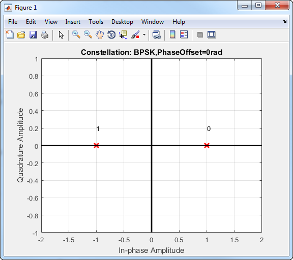
Phase modulation is a linear baseband modulation technique in which the message modulates the phase of a constant amplitude signal. Binary Phase Shift Keying (BPSK) is a two phase modulation scheme, where the 0’s and 1’s in a binary message are represented by two different phase states in the carrier signal
for where:
ϕn = πm + ϕ, m∈{0,1}.
ϕ is the initial phase offset.
Eb is the energy per bit.
Tb is the bit duration.
fc is the carrier frequency.
In MATLAB®, the baseband representation of a BPSK signal is
The BPSK signal has two phases: 0 and π.
The probability of a bit error in an AWGN channel is
where N0 is the noise power spectral density.
QPSK
In quadrature phase shift keying, the message bits are grouped into 2-bit symbols, which are transmitted as one of four phases of a constant amplitude baseband signal. This grouping provides a bandwidth efficiency that is twice as great as the efficiency of BPSK. The general QPSK signal is expressed as
where Es is the energy per symbol, Ts is the symbol duration, and ϕ is the initial phase offset. The complex baseband representation of a QPSK signal is
In this QPSK constellation diagram, each 2-bit sequence is mapped to one of four possible states. The states correspond to phases of π/4, 3π/4, 5π/4, and 7π/4.
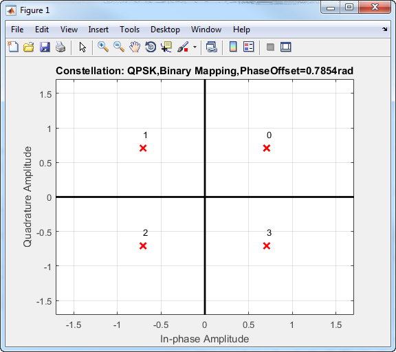
To improve bit error rate performance, you can map the incoming bits to a Gray-coded ordering. The primary advantage of the Gray code is that only one of the two bits changes when moving between adjacent constellation points. This table compares constellation point sequences for binary and Gray mapping.
| Binary-Coded Sequence | Gray-Coded Sequence |
|---|---|
| 00 | 00 |
| 01 | 01 |
| 10 | 11 |
| 11 | 10 |
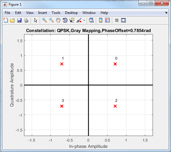
You can apply Gray codes to higher-order modulations, as shown in this Gray-coded QPSK constellation.
The bit error probability for QPSK in AWGN with Gray coding is
which is the same as the expression for BPSK. As a result, QPSK provides the same performance with twice the bandwidth efficiency.
Higher-Order PSK
For higher-order PSK constellations, the complex baseband form for an M-ary PSK signal using binary-ordered symbol mapping is
When the input is configured for bits, groups of log2(M) bits represent the complex symbols for the configured symbol mapping. The mapping can be binary encoded, Gray encoded, or custom encoded.
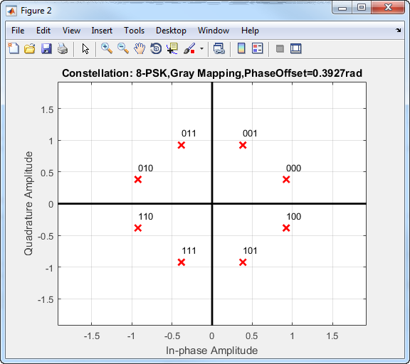
Gray coding has the advantage that only one bit changes between adjacent constellation points, which results in better bit error rate performance.
This 8-PSK constellation uses Gray-coded symbol mapping.
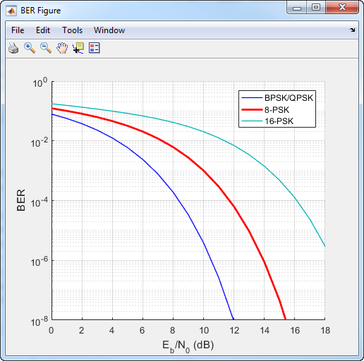
For modulation orders beyond 4, the bit error rate performance of PSK in AWGN worsens. In this bit error rate plot for Gray-coded mapping, the QPSK and BPSK curves overlap one another.
DPSK
DPSK is a noncoherent form of phase shift keying that does not require a coherent reference signal at the receiver. With DPSK, the difference between successive input symbols is mapped to a specific phase. As an example, for binary DPSK (DBPSK), the modulation scheme operates such that the difference between successive bits is mapped to a binary 0 or 1. When the input bit is 1, the differentially encoded symbol remains the same as the previous symbol, while an incoming 0 toggles the output symbol.
The disadvantage of DPSK is that it is approximately 3 dB less energy efficient than coherent PSK. The bit error probability for DBPSK in AWGN is Pb = 1/2 exp(Eb/N0).
OQPSK
Offset QPSK is similar to QPSK except that the time alignment of the in-phase and quadrature bit streams differs. In QPSK, the in-phase and quadrature bit streams transition at the same time. In OQPSK, the transitions have an offset of a half-symbol period as shown.
![]()
The in-phase and quadrature signals transition only on boundaries between symbols. These transitions occur at 1-second intervals because the sample rate is 1 Hz. The following figure shows the in-phase and quadrature signals for an OQPSK signal.
![]()
For OQPSK, the quadrature signal has a 1/2 symbol period offset (0.5 s).
The BER for an OQPSK signal in AWGN is identical to that of a QPSK signal. The BER is
where Eb is the energy per bit and N0 is the noise power spectral density.
References
[1] Rappaport, Theodore S. Wireless Communications: Principles and Practice. Upper Saddle River, NJ: Prentice Hall, 1996.
[2] Viterbi, A.J. “An Intuitive Justification and a Simplified Implementation of the MAP Decoder for Convolutional Codes.” IEEE® Journal on Selected Areas in Communications 16, no. 2 (February 1998): 260–64. https://doi.org/10.1109/49.661114.
See Also
Functions
Objects
Blocks
- Raised Cosine Transmit Filter | Raised Cosine Receive Filter | Bipolar to Unipolar Converter | Unipolar to Bipolar Converter | Data Mapper