Data Logging Techniques
Data logging enables real-time capture of signals from embedded hardware boards and platforms to be displayed and stored in the Simulation Data Inspector in Simulink®. Depending on the demands application being developed, data logging can be achieved in these three general configurations.
Standard data logging
Subsampled data logging
Multiprocessor data logging
These examples show minimal models for each of these data logging configurations and the
reasoning for each configuration type. All of these examples use the TI Delfino
F28379D hardware board, however these techniques can be used with any
supported SoC Blockset™ hardware board or platform.
Standard Data Logging
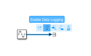
This example shows how to configure an SoC Blockset model to log data from hardware when the model is deployed to a TI Delfino F28379D LaunchPad. The system contains a single timer-driven task that consists of a Sine Wave block connected to a Terminator block. To log the output signal from the Sine Wave block, select the signal line, click the ellipsis, and select Enable Data Logging. This selection automatically registers this signal to be logged from the model during simulation and to be displayed to the Simulation Data Inspector. Open the model by executing this code.
open_system("defaultDataLogging_top.slx")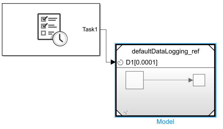
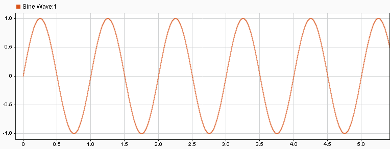
Use the SoC Builder tool to deploy the model to the TI Delfino F28379D LaunchPad. A host-target communication connection, set up by the SoC Builder, enables data to be automatically logged from the executable running on the hardware board to the Simulation Data Inspector in Simulink. This image shows the logged data signal from the model deployed to a TI Delfino F28379D LaunchPad.
Subsampled Data Logging
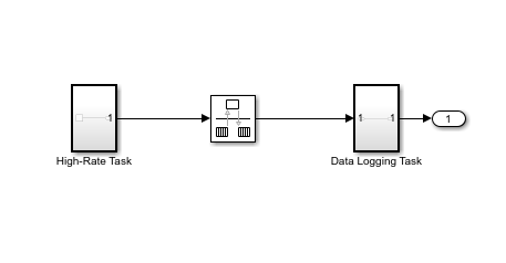
This example shows how to configure a resource intensive SoC Blockset model to log data from hardware when the model is deployed to a TI Delfino F28379D LaunchPad. The system contains two timer-driven tasks. The first task consists of a Sine Wave block connected to a Terminator block that represents a task running at a high rate. The second task uses a Rate Transition block to subsample and log the signals from the high-rate task.
open_system("slowerRateDataLogging_top.slx")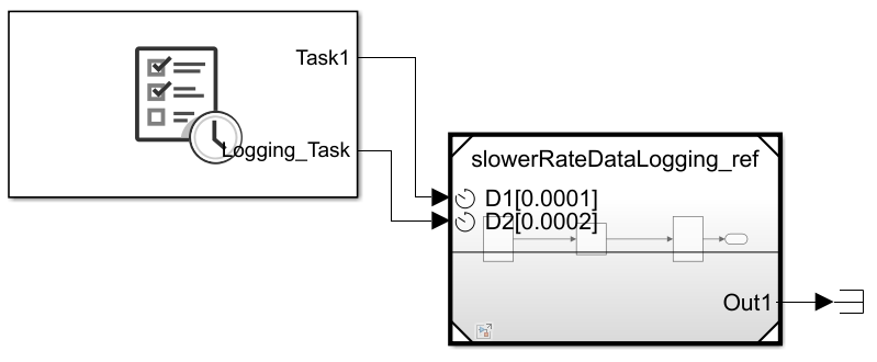
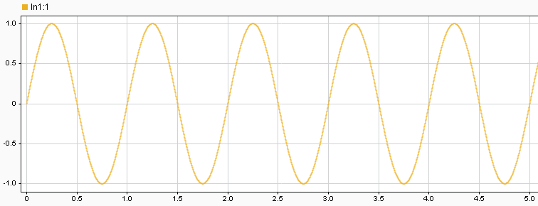
Use the SoC Builder tool to deploy the model to the TI Delfino F28379D LaunchPad. A host-target communication connection, set up by the SoC Builder, logs the subsampled data from the executable running on the hardware board and sends the data to the Simulation Data Inspector in Simulink. By enabling data logging in the slower, low-priority task, data can be captured on hardware from the resource intensive, high-priority task without interfering with its behavior or reaching the limits of the host-target communication system. This image shows the subsampled logged data signal from the model deployed to a TI Delfino F28379D LaunchPad.
Multiprocessor Data Logging
This example shows how to configure a resource intensive SoC Blockset model to log data from hardware when the model is deployed to a TI Delfino F28379D LaunchPad. The system contains two timer-driven tasks divided across two processors. Task 1 (on processor 1) consists of a Sine Wave block connected to a Terminator block and represents a high-rate, resource intensive task. An Interprocess Data Channel block connects processor 1 and 2, providing data transfer between the processors. Task 2 (on processor 2) logs signals transferred from task 1 back to Simulink.
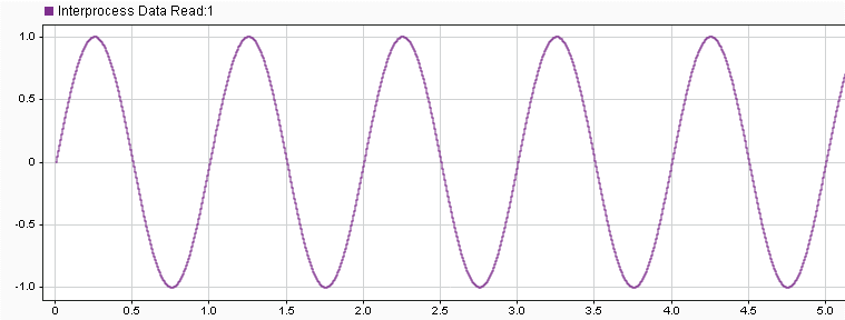
open_system("otherCPUDataLogging_top.slx")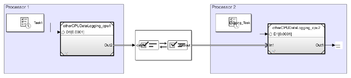 Use the SoC Builder tool to deploy the model to the TI Delfino F28379D LaunchPad. A host-target communication connection, set up by the SoC Builder, logs the signal data from the executable running on processor 2 of the hardware board and sends the data to the Simulation Data Inspector in Simulink. Using processor 2 to own and manage the host-target communication and data logging, data can be captured from the resource intensive, high-priority task on processor 1 without interfering with its behavior and enabling that task to consume most of the processor resources yet maintain quality of the data logging to Simulink. This image shows the logged data signal from task 1 on processor 1, captured on task 2 on processor 2, of the model deployed to a TI Delfino F28379D LaunchPad.
See Also
Simulation Data Inspector | SoC Builder | Interprocess Data Channel
You can also select a web site from the following list:
Americas
- América Latina (Español)
- Canada (English)
- United States (English)
Europe
- Belgium (English)
- Denmark (English)
- Deutschland (Deutsch)
- España (Español)
- Finland (English)
- France (Français)
- Ireland (English)
- Italia (Italiano)
- Luxembourg (English)
- Netherlands (English)
- Norway (English)
- Österreich (Deutsch)
- Portugal (English)
- Sweden (English)
- Switzerland
- United Kingdom (English)