Serial Communication Using SCI Blocks
This example shows how to use the SCI blocks to set up serial communication between the target hardware and your host computer for C2000™ Microcontroller Blockset.
Introduction
Using this example, you will:
Establish communication between the target hardware and the host computer using SCI Transmit and Receive blocks on the target hardware and Instrumentation Control Toolbox™ Serial Transmit and Receive blocks on the host.
Establish communication between the target hardware and the host computer using SCI Transmit and Receive blocks on the target hardware and a MATLAB® script on the host.
Use the polling and interrupt methods to receive data on the target hardware.
Use frame size to transmit data when the transmit rate is faster than the receive rate.
Serial communication with data exceeding FIFO length.
You can also use the model c28x_sci_comm_interrupt_TopModel.slx to perform Model Reference workflow. For more information, see Model Reference Support for C2000 Processors.
Prerequisites
Complete the following tutorials:
Set Up Serial Communication with Target Hardware. There are different control card versions available for C2000™ processors. In some control cards, the SCI_A module pins are directly connected to the USB docking station and other control cards have a MAX32xx chip for RS-232 communication on the control card.
Required Hardware
Any Texas Instruments C2000 board
Serial Communication between Host Computer and Target Hardware using Serial Transmit and Receive Blocks on Host
In this task, you can transmit counter data from the host to the target hardware using Simulink® model on the host. When the target hardware receives data on polling, it transmits the same data back to the host. The host then displays the transmitted and received signals.
Target Model
1. Open the target c28x_sci_comm.slx model.

2. The example model is configured for the TI Piccolo F28069M launchpad. To select different target hardware, in the Simulink® Editor, browse to Configuration Parameters > Hardware Implementation > Hardware board.
3. Navigate to Hardware Implementation > Target Hardware Resources > SCI_A and set the Baud rate to 115200.

4. The model is configured to receive the data without header and terminator at a sample time of 0.001 s and to transmit the same data.
5. Following figure shows the SCI block configurations for the target model. Double-click on the blocks to open block parameter configurations. Ensure the specified parameter values are the same if you want to run this example for other hardware boards.
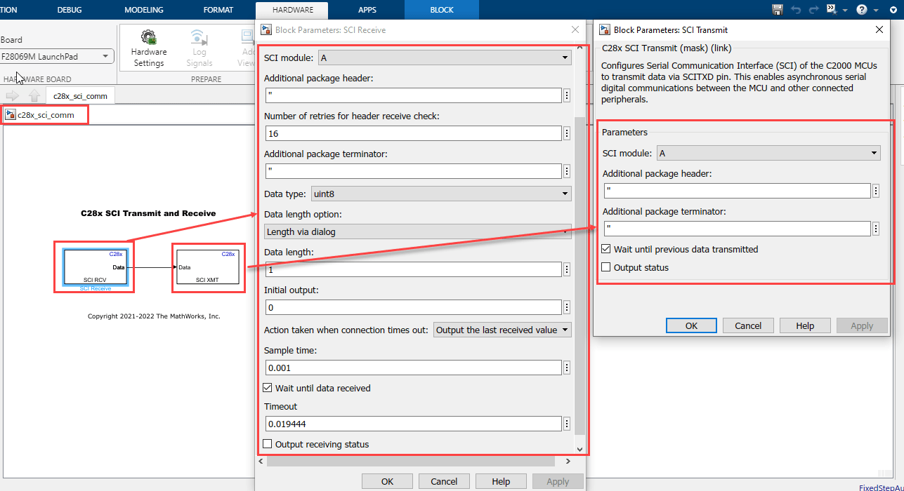
Things to consider
You must consider the following things when configuring the SCI Receive block. In this example, the c28x_sci_comm.slx model is configured to Wait until data received with timeout for blocking mode.
Blocking mode - Select the Wait until data received parameter and set Timeout to
inf. In this mode, if data is not available in FIFO to read, the block waits for infinite time until the data is available to read.Blocking mode with Timeout - Select the Wait until data received parameter and set Timeout to
any finite value greater than 0. In this mode, if data is not available in FIFO to read, the block checks the FIFO status until the timeout value is reached. If data is not available in FIFO to read within that time, then the SCI Receive block outputs its status as timeout.Non-Blocking mode - Do not select the Wait until data received parameter. In this mode the SCI Receive block reads the data if the data is available in FIFO; otherwise the block outputs its status as Data not available.
In order to receive data of length more than the FIFO length, use either blocking mode or blocking mode with timeout. This ensures extra time to get the remaining data in FIFO after reading the entire FIFO.
In blocking mode with and without timeout enabled, you might encounter task overrun as it waits for the data to read.
6. Click Build, Deploy & Start in the Hardware tab or press Ctrl+B to build and download the executable file.

Run Host Model
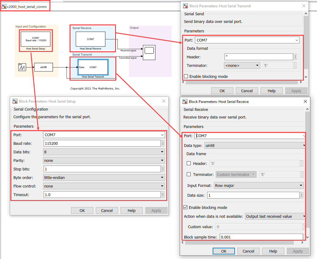
1. Open the host c2000_host_serial_comm.slx model.

2. To see the list of available COM ports on your computer, select Start > Control Panel > Device Manager > Ports (COM & LPT).
Note: The COM port shown in the figure is for illustration purpose and might vary for your computer. Select the COM port applicable for you computer.

3. Configure the device for Host Serial Setup, Host Serial Transmit, and Host Serial Receive blocks. Ensure that you set the baud rate to 115200 in the Host Serial Setup block.
4. Set the Stop time to Inf and click on Run drop-down and enable the Simulation Pacing in order to ensure real time communication with target.

5. Click Run
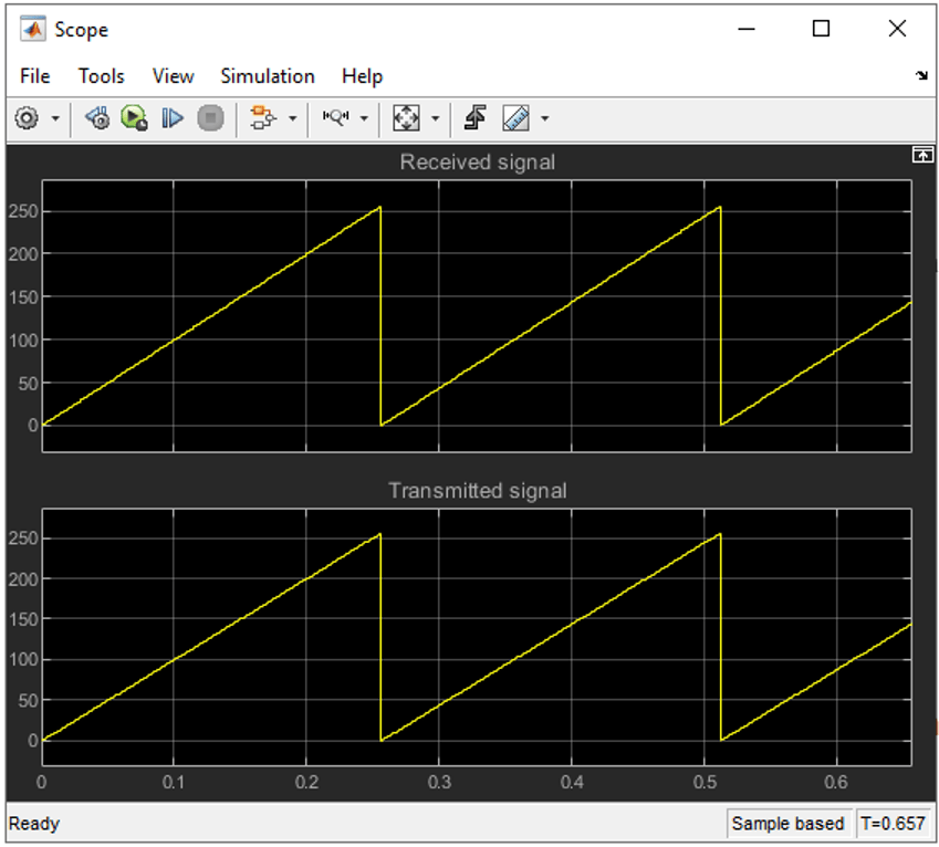
6. Compare the serial data received from the target hardware and transmitted from the host.
Serial Communication between Host Computer and Target Hardware Using MATLAB Script on Host
In this task, you will transmit uint8 data from the host to the target hardware using a MATLAB® script on the host. When the target hardware receives the data on interrupt, it transmits the same data back to the host. The host then displays the received data in the MATLAB command window.
Target Model
1. Open the target c28x_sci_comm_interrupt.slx model.
2. The example model is configured for the TI Piccolo F28069M launchpad. To select a different target hardware, in the Simulink® Editor, browse to Configuration Parameters > Hardware Implementation > Hardware board.
3. Navigate to Hardware Implementation > Target Hardware Resources > SCI_A and ensure that you set the Baud rate to 115200.
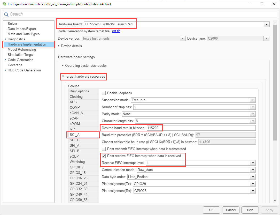
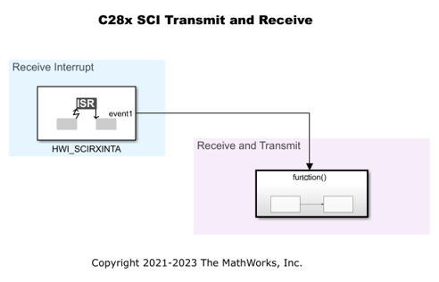
4. Target hardware receives the data on interrupt. SCIA_RX is used to receive on interrupt level 1.
5. Following are the SCI block configurations for the target model. Double-click on the blocks to open block parameter configurations. Follow the section Things to consider from Task 1. Ensure that the specified parameter values are the same if you want to run this example for other hardware board. In this example, the c28x_sci_comm_interrupt.slx model is configured to Wait until data received with timeout for blocking mode.
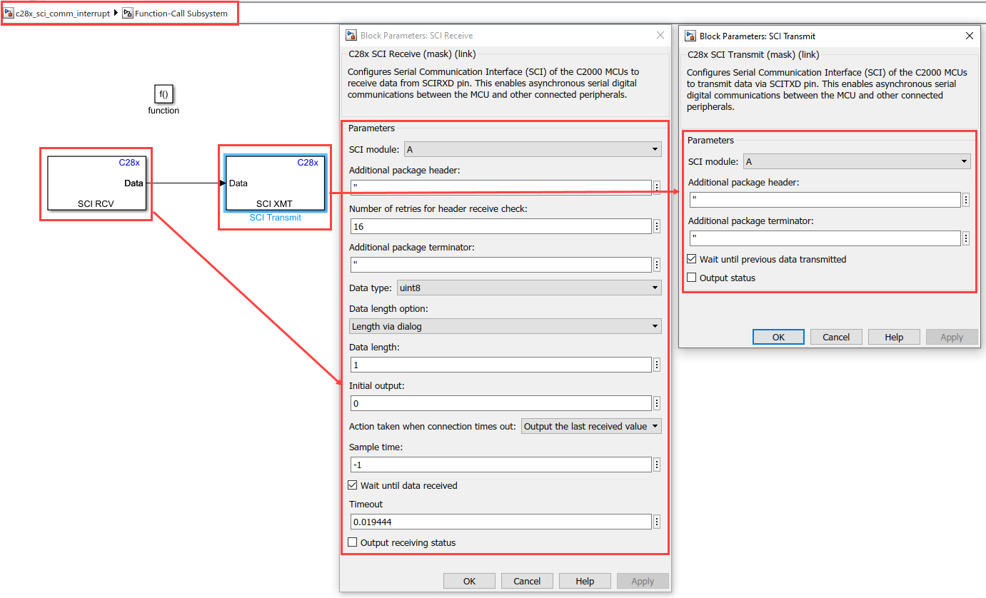
6. On receiving the new data, an interrupt is triggered, and the target hardware transmits the received data.
7. Click Build, Deploy & Start in the Hardware tab or press Ctrl+B to build and download the executable file.
Run on Host Using MATLAB Script
1. To run the model on host using MATLAB script, use COM port as an input argument and baud rate as an optional input argument. If baud rate is not provided, then by default a 115200 baud rate is used.
2. To see the list of available COM ports on your computer, select Start > Control Panel > Device Manager > Ports (COM & LPT).
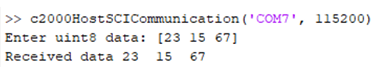
3. Run the following command at the MATLAB command prompt. Provide the COM port number of your computer. For example,
c2000HostSCICommunication('COM7', 115200);
4. Provide uint8 data as an input in response to the prompt.
5. Observe that the same data is received in the MATLAB® command window.
Use Frame Size to Transmit Data
In this task, you can transmit frame of data of size more than from the host to the target hardware using Simulink® model on the host. The host then displays the transmitted signal at a slower rate.
Target Model
1. Open the target c28xsciframetx.slx model.
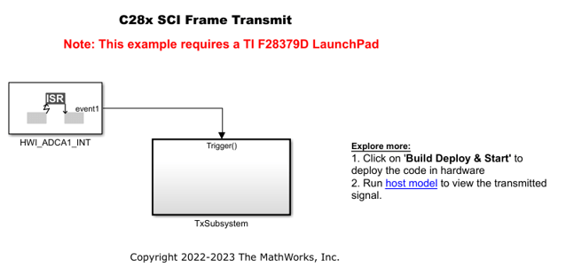
2. The example model is configured for the TI Delfino F28379D launchpad. To select a different target hardware, in the Simulink® Editor, browse to Configuration Parameters > Hardware Implementation > Hardware board.
3. Navigate to Hardware Implementation > Target Hardware Resources > SCI_A and ensure that you set the Baud rate to 5e6.

4. The model is configured to receive the data with header and terminator at a sample time of 0.03s and the data is transmitted at a rate determined by ADC interrupt which is 5e-6.
5. Following are the SCI block configurations for the target model. Double-click on the blocks to open block parameter configurations. Ensure the specified parameter values are the same if you want to run this example for other hardware boards.
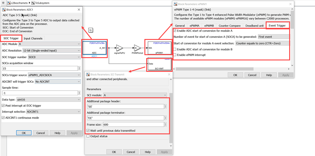
You will transmit data of frame size more than 1 at the rate determined by the ADC interrupt. The data fed to DAC is read by ADC which is then transmitted through SCI transmit block. The ADC then sends the interrupt after the conversion is completed. The start of conversion of ADC is triggered by ePWM1. The transmitted data is received in the host model at a slower rate (0.03sec).
6. Click Build, Deploy & Start in the Hardware tab or press Ctrl+B to build and download the executable file.
Run on Host Model
1. Open the host c28xsciframehostmodel.slx model.

2. To see the list of available COM ports on your computer, select Start > Control Panel > Device Manager > Ports (COM & LPT).
3. Configure the device for Host Serial Setup, and Host Serial Receive blocks. Ensure that you set the baud rate to 5.625e6 in the Host Serial Setup block.
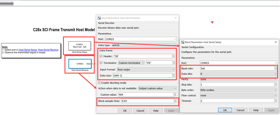
4. Click Run. Observe the data received on the Scope.
Serial Communication with Data Exceeding FIFO Length
Facilitate data transfer between the host and target by utilizing a buffer on the target to manage data sizes exceeding the FIFO capacity. For more information on buffer implementation, see Buffer Logic for Data Transmission.
Target Model
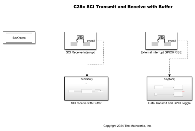
1. Open the target c28xSCIRxDataWithBuffer.slx model.
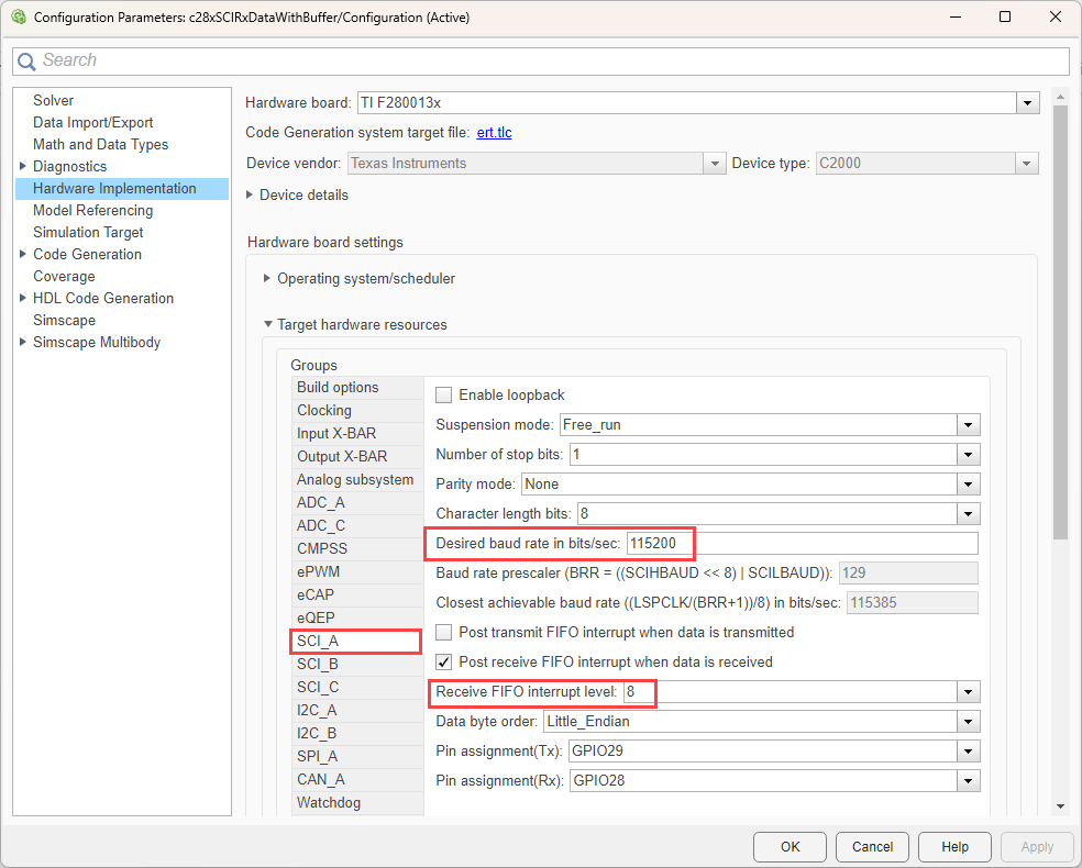
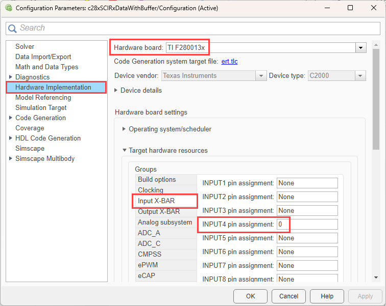
2 The example model is configured for the TI F280013x ControlCard. To select different target hardware, in the Simulink®, browse to Configuration Parameters > Hardware Implementation > Hardware board.
3. Navigate to Hardware Implementation > Target Hardware Resources > SCI_A and set the Baud rate to 115200.
4. Choose a FIFO level that aligns with the buffer size and ensure the buffer and FIFO sizes are multiples of the FIFO level. In this example, the Receive FIFO interrupt level is set to 8.
The following explanation details how FIFO level 8 was determined.
FIFO Level Optimization
To optimize data transmission and prevent data loss, configure the FIFO (First-In-First-Out) level as a perfect multiple of both the processor's FIFO size and the buffer size. Additionally, set the FIFO level to handle only 50% of its capacity to avoid overflow and ensure reliable data handling.
Suppose you want to transmit 100 uint32 data elements using a TI F280013x hardware board with a FIFO size of 16 bytes.
100 uint32 data elements, corresponds to 400 bytes. If you configure the FIFO level to 2 uint32 elements, it corresponds to 8 bytes. For a FIFO level of 8 uint32 elements, the FIFO utilization is 50%, ensuring no data loss. This configuration works well because the buffer size of 400 bytes is a multiple of the FIFO level.
Suppose you want to handle data which are odd number of bytes.
For example, if the buffer size is 93 bytes, the only valid multiple of 93 is 1. In this case, set the FIFO level to 1 and configure the SCI receive block to read uint8 data with a length of 1 inside the ISR. To receive 100 uint32 data elements, which correspond to 400 bytes.
5. Assign GPIO pin: Set INPUT4 pin to 0 (e.g., using GPIO 0).
6. Following figure shows the target model configurations. Double-click on the blocks to open block parameter configurations. Ensure the specified parameter values are the same if you want to run this example for other hardware boards.
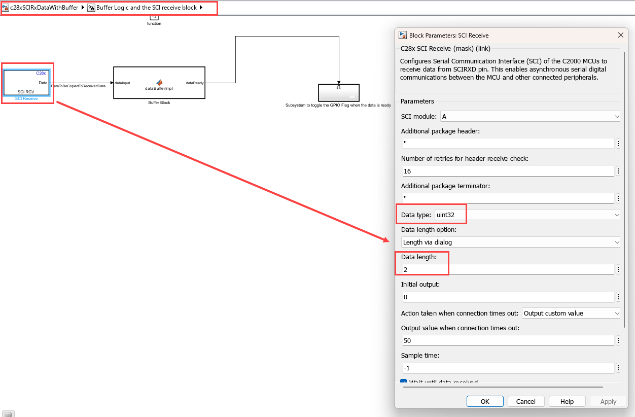
SCI Receive Block
The SCI Receive block is set to receive two uint32 values at a time.
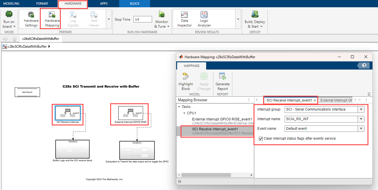
SCI Interrupt and External Interrupt via Hardware Mapping
Click Hardware Mapping in the Hardware tab and configure SCI Receive Interrupt and External Interrupt.
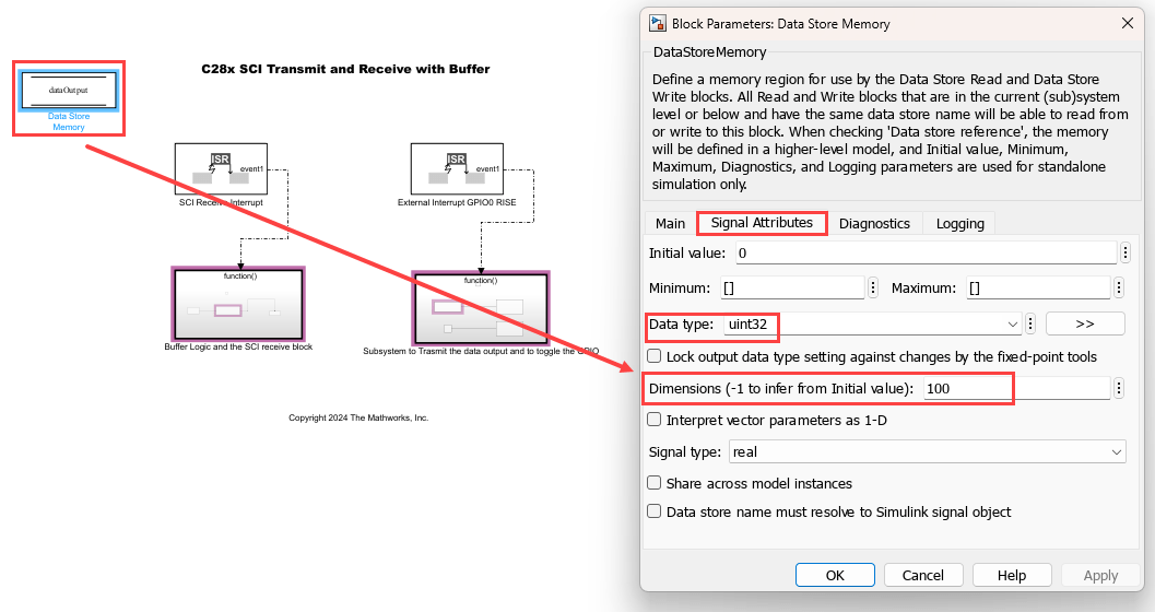
Data Store Memory Block
In the Data Store Memory block, set the Data type to uint32 and Dimensions to 100.
Updates required to handle different data than default
Perform these updates in the example to receive a different set of data type and buffer size.
Update the data type and data length of SCI Receive block with new values.
Calculate appropriate FIFO level to trigger ISR and set the value. Navigate to Configuration Parameters > Hardware Implementation > Target Hardware Resources > SCI_A and set the Receive FIFO interrupt level.
Update
bufferSizein MATLAB functiondataBufferImpl.Update the data store memory block
dataOutputwith matching data type and buffer size.
7. Click Build, Deploy & Start in the Hardware tab or press Ctrl+B to build and download the executable file.
Run Host Model
1. Open the host c28xSCIRxDataWithBufferHostModel.slx model.
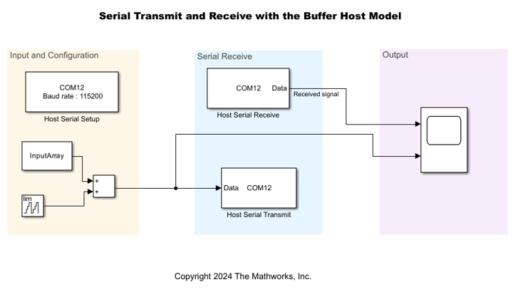
2. Select the COM port applicable for you computer. To see the list of available COM ports on your computer, select Start > Control Panel > Device Manager > Ports (COM & LPT).
3. Configure the device for Host Serial Setup, Host Serial Transmit, and Host Serial Receive blocks. Ensure that you set the baud rate to 115200 in the Host Serial Setup block.
4. Set the Stop time to Inf and click on Run drop-down and enable the Simulation Pacing in order to ensure real time communication with target.
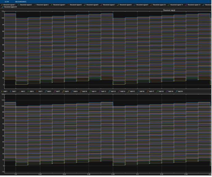
5. Click Run.
6. Compare the serial data received from the target hardware and transmitted from the host.
Things to Consider
Ensure data processing is faster than serial data reception to prevent data loss.
Consider implementing full handshaking to control data reception and align it with the processing speed. For more information, see Interface LCD Booster Pack with Texas Instruments C2000 Processors.
Other Things to Try
Send and receive counter data using the Simulink® host model
c2000_host_serial_comm.slxwhile runningc28x_sci_comm_interrupt.slxon the target.Use the c2000HostSCICommunication MATLAB script to send and receive uint8 data while running
c28x_sci_comm.slxon the target.