Reutilizar las funciones de Simulink en gráficos de Stateflow
Una función de Simulink® es un objeto gráfico que permite llamar a un subsistema de Simulink en las acciones de estados y transiciones. Las funciones de Simulink no se admiten en gráficos de Stateflow® independientes en MATLAB®.
Las funciones de Simulink pueden mejorar la eficiencia del diseño e incrementar la legibilidad del modelo. Entre las aplicaciones habituales se incluyen:
Definir una función que requiere bloques de Simulink
Planificar la ejecución de varios controladores
Las funciones de Simulink de un gráfico de Stateflow proporcionan las siguientes ventajas:
No requieren bloques de subsistema de llamada a función
No requieren eventos de salida
No requieren líneas de conexión
Una función de Simulink puede residir en cualquier parte de un gráfico, estado o subgráfico. La ubicación de una función determina qué estados y transiciones pueden llamar a la función.
Si desea llamar a la función dentro de un solo estado o subgráfico y sus subestados, coloque la función de Simulink en ese estado o subgráfico. Esa función anula cualquier otra función del mismo nombre en los elementos principales de ese estado o subgráfico.
Si desea llamar a la función desde cualquier lugar de un gráfico, coloque la función de Simulink en el nivel del gráfico.
Si desea llamar a la función desde cualquier gráfico del modelo, utilice un bloque Simulink Function (Simulink) para definir la función directamente en el área de diseño de Simulink. Para obtener más información, consulte Simulink Functions Overview (Simulink).
Para acceder a los datos de Stateflow desde la función de Simulink, debe incluir esos datos como una entrada en la función de Simulink.
Esta función de Simulink se denomina sim_fcn. Toma tres argumentos (a, b y c) y devuelve dos valores de salida (x e y).

La función contiene un subsistema de Simulink que multiplica el primer argumento por una ganancia de 25 y combina los otros dos argumentos en una señal de salida compleja.

Una vez que tenga la función de Simulink definida, la puede colocar en cualquier parte del gráfico de Stateflow o del modelo de Simulink. Además, puede reutilizar esta función tantas veces como sea necesario dentro del mismo modelo o de distintos modelos.
Nota
No puede llamar a las funciones globales de Simulink desde un gráfico de Stateflow dentro de una referencia de modelo. Para resolver este problema, cree una nueva función de Simulink en el gráfico de Stateflow. Dentro de esta función de Simulink, incluya un bloque Function Caller que llame a la función global original de Simulink. Para obtener más información sobre el bloque Function Caller, consulte Function Caller (Simulink).
Definir una función de Simulink
En la paleta de objetos, haga clic en el icono de función de Simulink
 .
.En el área de diseño del gráfico, haga clic en la ubicación de la nueva función de Simulink.
Introduzca la etiqueta de firma de la función.
La etiqueta de firma de la función especifica un nombre para la función y los nombres formales de sus argumentos y valores devueltos. Una etiqueta de firma tiene la siguiente sintaxis:
Puede especificar varios valores devueltos y varios argumentos de entrada. Cada valor devuelto y cada argumento de entrada puede ser un escalar, un vector o una matriz de valores. Para funciones con solo un valor devuelto, omita los corchetes en la etiqueta de firma.[return_val1,return_val2,...] = function_name(arg1,arg2,...)Debe utilizar nombres de variable únicos para todos los argumentos y valores devueltos.
Para programar la función, abra el editor de Simulink haciendo doble clic en el cuadro de funciones. Inicialmente, el editor contiene un bloque de llamada a función Trigger (Simulink) y los bloques Inport (Simulink) y Outport (Simulink) que coinciden con la firma de función. No puede eliminar el bloque Trigger.
En el editor de Simulink, añada bloques para crear un subsistema de Simulink y conéctelos a los bloques Inport y Outport.
Configure los bloques Inport y Outport.
Haga doble clic en cada bloque para abrir el cuadro de diálogo Block Parameters.
En la pestaña Signal Attributes, introduzca Data type y Port dimensions del parámetro de entrada o valor devuelto.
Haga clic en OK.
Nota
Un bloque Inport en una función de Simulink no puede heredar el Data type ni Port dimensions. Para obtener más información, consulte Pautas de uso de funciones de Simulink.
Llamar a las funciones de Simulink en estados y transiciones
Puede llamar a las funciones de Simulink desde las acciones de cualquier estado o transición o desde otras funciones.
Para llamar a una función de Simulink, utilice la firma de función e incluya un valor de argumento para cada argumento formal en la firma de función.
[return_val1,return_val2,...] = function_name(arg1,arg2,...)Si los tipos de datos de los dos argumentos difieren, la función convierte el argumento al tipo del argumento formal.
Especificar las propiedades de las funciones de Simulink
Puede modificar las propiedades de una función de Simulink en el cuadro de diálogo Block Parameters.
En el editor de Stateflow, haga clic con el botón secundario sobre la función de Simulink.
Seleccione Properties.
Edite las propiedades de la función de Simulink.
También puede modificar estas propiedades en Model Explorer. Para obtener más información, consulte Model Explorer (Simulink).
Para obtener una descripción de las propiedades de la función de Simulink, consulte Subsystem (Simulink).
Puede especificar propiedades adicionales de las funciones de Simulink de forma programática usando objetos Stateflow.SLFunction. Para obtener más información sobre la interfaz programática de Stateflow, consulte Visión general de la API de Stateflow.
Utilizar una función de Simulink para acceder a los bloques de Simulink
En este ejemplo, puede comparar el modelado de la lógica de cambio de un sistema de un automóvil. El primer modelo no utiliza las funciones de Simulink, mientras que el segundo lo utiliza.
Modelo sin una función de Simulink
Este modelo utiliza un subsistema de llamada a función, run(), un modelo de Simulink para calcular el umbral de cambio de marchas. El gráfico de Stateflow utiliza un evento de salida, CALC_TH(), para llamar al subsistema.

Para obtener más información sobre subsistemas de llamada a función, consulte Using Function-Call Subsystems (Simulink).
Modelo con función de Simulink
Se puede obtener esta misma funcionalidad con una función de Simulink. En este gráfico de Stateflow, se utiliza la función de Simulink calc_th para calcular el umbral.

La acción during en selection_state contiene una llamada de función a calc_th, que contiene bloques de Simulink.
Este método de modelado minimiza los objetos del modelo.

Para obtener más información sobre este ejemplo, consulte Model a Car with Automatic Transmission.
Utilizar una función de Simulink para planificar la ejecución de varios controladores
En este ejemplo, puede comparar dos maneras de planificar la ejecución de varios controladores. El primer modelo no utiliza las funciones de Simulink, mientras que el segundo lo utiliza.
Modelo sin funciones de Simulink
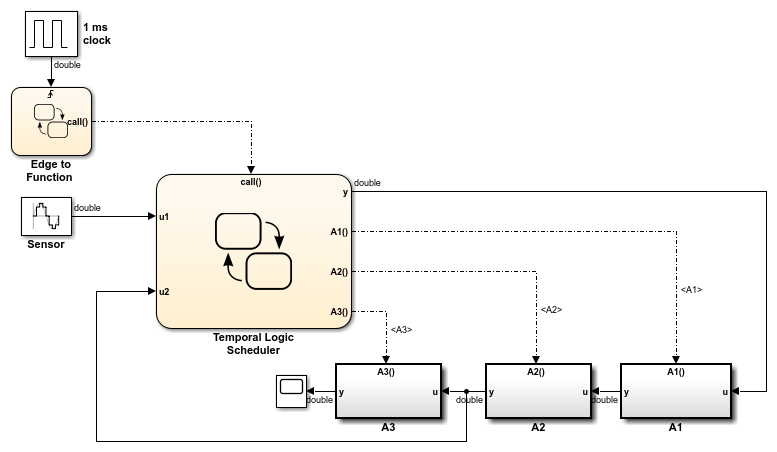
Este modelo utiliza subsistemas de llamada a función para modelar cada controlador. El modelo incluye eventos de salida en un gráfico de Stateflow para programar la ejecución de los subsistemas.

Para cada evento de salida, se necesita una línea de conexión para conectar el gráfico de Stateflow con el subsistema de llamada a función correspondiente.
Método de modelado con funciones de Simulink
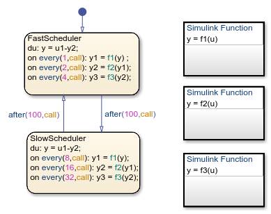
Cada controlador puede también modelarse con una función de Simulink en un gráfico de Stateflow. Este modelo utiliza llamadas a función para planificar la ejecución de los subsistemas.

Este método de modelado minimiza los objetos del modelo.

Para obtener más información sobre este ejemplo, consulte Planificar subsistemas para ejecutarlos en momentos específicos.
Pautas de uso de funciones de Simulink
 Utilizar caracteres alfanuméricos y guiones bajos en los nombres de los argumentos
 Establecer explícitamente las propiedades de bloques Inport
 Convertir señales no contiguas a señales contiguas
 No utilizar las funciones de Simulink en los diagramas de Moore
 No llamar a las funciones de Simulink en transiciones predeterminadas que se ejecutan durante la inicialización del gráfico
 No llamar a las funciones de Simulink en acciones de estado
 During o condiciones de transición de los gráficos de tiempo continuo
Consulte también
Simulink Function (Simulink) | Trigger (Simulink) | Inport (Simulink) | Outport (Simulink) | Signal Conversion (Simulink) | Bus Creator (Simulink) | Mux (Simulink)