How to Work with SCIs on C2000 MCUs for Debugging | Getting Started with C2000 Microcontroller Blockset, Part 16
From the series: Getting Started with C2000 Microcontroller Blockset
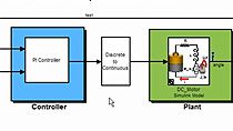
Learn how to use an SCI interface on a TI C2000™ MCU to transmit and receive data back into Simulink® from an F28379D LaunchPad™ to control the signals on the TI C2000 MCU and also read data from the hardware using C2000 Microcontroller Blockset. This is a continuation to another video in this series, “Monitor and Tune GPIOs, ADCs, DACs, and ePWMs on C2000 MCUs.”
Published: 13 Jan 2025
Next, let's see how to use the serial UART, or what we call serial communication interface, on the C2000 MCU. To demonstrate this capability, I will be creating two models. One is the target model that will be deployed on the hardware. And the other will be a host model that will be running on the host computer with Simulink. And then we can use the host model running on Simulink to communicate with the C2000 MCU over SCI communication using the USB cable connected to it.
Let's iterate on what we have created so far to create the target model. Delete all the constant blocks and logics we created for the peripheral blocks. Then add the F2837xD SCI transmit and SCI receive blocks into the model. And connect the output of the ADC port to the input of the SCI transmit block.
Configure the SCI transmit block to use the SCI A module. And leave the rest of the parameters to default settings. Note down that we have the additional header character S and the terminator with character E. We have to match these values while we build the host model.
Similarly, configure the SCI receive block with SCI module A. And set the data type to uint16, as we are going to connect the output of this block to the input of the digital output, DAC and ePWM. And the data type of these input ports of the peripheral blocks are of data type uint16.
Then set the data length to 4 and sample time to minus 1. Then click on OK. The reason to set this value is because we are going to read data via SCI from the host model to give input signal to the four peripheral blocks that we have here, the two digital output blocks, one DAC, and one ePWM block.
Let us use the hardware interrupt mechanism to receive serial data using SCI receive block. To do this, we need to go to the hardware settings. And under Target hardware resources, you can configure the SCI module configuration. And enable the post receive FIFO interrupt when data is received option. The reason to use the SCI A module is because the F28379D LaunchPad has the SCI module connected to onboard debugger of the LaunchPad, which we can use to communicate with the F28379D C2000 MCU over the USB from the PC running Simulink, just like how we did with monitor and tune capability.
Next, let us bring in the hardware interrupt block into the model and configure it. Click on Hardware Mapping. And this will launch the new window where you can configure the interrupt service routine. Select the interrupt group as SCI and interrupt name as SCIA RX interrupt. And check Clear interrupt status flags after event service. And click on Apply Changes.
What this does is whenever there is any data received on the SCI receive buffer, it will trigger a hardware interrupt. So to use this trigger signal, we need to introduce a function call subsystem into the model. And we have to move the SCI receive block inside that. So whenever there is any data received via serial, the interrupt will be triggered. And the SCI receive block will read the data and output it.
We can use a demux to separate out the signals we want to send from the host model to the target model. Now you can click on Build, Deploy, and Start to generate code and deploy this model on the hardware.
Since hardware interrupt-driven code is asynchronous, you will see the following error. To fix this, introduce a rate transition block. And uncheck Ensure data integrity option in the rate transition block. And click on Apply. And then build and deploy the model on the hardware.
Once the model is deployed, we can go ahead and create the host model. To do that, create a new model. And save the model as Host_Model. Then open the C2000 Microcontroller Blockset library. And drag and drop the Host Communication blocks into the model. You have the Serial Configuration, Serial Send, and Serial Receive blocks.
The serial configuration block is where you need to configure multiple parameters, like the baud rate, component you want to use, data bit parity, byte order, and so on, just like you would do with any serial terminal software. Now, to configure this, we need to go back to the target model and check what was the baud rate that was mentioned as default in the target hardware configuration. As you can see here, the desired baud rate that was set was 5e6.
Let us set the same value as the baud rate in the serial configuration in the host model. And set the timeout to 10 milliseconds. And click on Apply. The reason for doing this is if you set the timeout to 10 seconds or such a high value, in case there is no data on the serial receive block, the model will wait for 10 seconds to run the next step in the simulation. By reducing this value, we can see real-time action and log data on Simulink faster.
Now let's connect a display block to the serial receive block. And configure the serial receive block. Configure the header and terminator with the values we provided for the SCIA transmit block here. So it was the character S for the header and character E for the terminator.
Select the data type to uint16 and the COM port to COM23, which is the COM port of the LaunchPad. Then select the input format to row major. And set the data size to 1, as we are currently sending only one signal from the hardware to the host machine, which is the ADC signal. Click on Apply and OK.
Now connect the output port of the serial receive block to the input port of the display block. Next, let us add four constant blocks and connect it to a mux. Then connect the output of the mux to the input of the serial send block.
Then configure the serial send block with the header ASCII code of 83 and terminator ASCII code of 69, which is the equivalent of character S and E, which we have used as header and terminator in the SCI receive block in the target model. Also, select the correct COM port. Click on Apply and OK.
Now when you run this host model, you can see that you are receiving some value from the C2000 MCU which is transmitted over UART, which is nothing but the raw ADC count signal which we connected to the SCI transmit block in the target model. But when you try to change the constant values, you don't see any change in the LED state, neither there is any DAC output value or a PWM signal generated. The reason for this is data type mismatch.
Let's look at the target model and the host model side by side to understand this. So the host model uses mux to create an array of serial data and sends it to the C2000 MCU over the COM port. And as mentioned earlier, whenever this data is received on the C2000 MCU SCI buffer, an interrupt is triggered. And the received data is read and demuxed on the hardware side and given as input signal to the corresponding peripheral blocks.
The same way, whenever any data is received on the host side from the MCU, the data is displayed on the host machine. We need to make sure that the data type of the signal we send matches the expected data type on the receiving side. As I mentioned earlier, the peripheral blocks needs an input signal of data type uint16. So let's change the constant values to uint16 data type on the host model.
Now if you run the host model, you can see that you are able to see the LED status change when you change the constant value on the host model. When you change it to 1, the LED goes off. And when you change it back to 0, the LED turns on.
Similarly, you can see that when the fourth constant value is changed, the ePWM signal is generated at 25% and 50% duty cycle. Now you can add the logic which we used earlier to generate DAC voltage and read ADC voltage in the host module itself. And then run the model to verify and see how that works.
You could also add Simulink dashboard blocks and connect it to the constant block and model change detection logic to send data to the hardware only when there is a change detected, instead of sending it continuously, to improve the execution speed and visualizations.
In this demo model that I have created, I am using a knob to set the DAC voltage from 0 to 3 volts. And the same is displayed on the gauge, which measures the DAC voltage using the ADC. So as I vary the voltage using the knob, you can see that the ADC is also measuring the same voltage. And it matches with the voltage measured by the multimeter.
Then I can use the slider to vary the duty cycle of the PWM signal that is generated. You can see it as a variable duty cycle on the slider. The duty cycle of the PWM signal changes, which you can witness on the scope.
You can check the rates at which the model is running using the colors option. And then fix your model to run at a single fast rate if possible, to have smooth and faster data exchange between the hardware and the host model. Now when you run the model, you will notice that the data transfer is faster than what it was earlier. You can also use the toggle switch dashboard blocks to switch on and switch off the onboard LEDs of the LaunchPad for better visualization.
With that, we come to the end of this video, where you learned how to use GPIO, ADC, DAC, ePWM, and serial communication with hardware interrupt. As something to experiment beyond this, I would suggest you to try sending multiple data from hardware to host using mux on the hardware side and demux on the host side, as I have shown here.