Using the Single Camera Calibrator App
R2026bCamera Calibrator Overview
You can use the Camera Calibrator app to estimate camera intrinsic parameters. You can use these camera parameters for various computer vision applications. These applications, such as removing the effects of lens distortion from an image, measuring planar objects, or reconstructing 3-D scenes from multiple cameras.

Use this workflow to calibrate your camera and to follow best practices to prepare and capture calibration images and to evaluate calibration accuracy.
The Camera Calibrator app incorporates a suite of functions to implement the camera calibration workflow. You can use these functions directly in the MATLAB® workspace. For a list of these functions, see the Calibrate Cameras topic.
Choose a Calibration Pattern
The Camera Calibrator app supports checkerboard, circle grid, AprilTag, ChArUco, and custom detector patterns. For details on each of these patterns and PDF files containing printable patterns, see Calibration Patterns. The app can calibrate cameras with a field of view (FOV) of up to 195 degrees.
Capture Calibration Images
For best calibration results, use between 10 and 20 images of the calibration pattern. The calibrator requires at least three images. Use uncompressed images or lossless compression formats such as PNG. The calibration pattern and the camera setup must satisfy a set of requirements to work with the calibrator. For more details on camera setup and capturing images, see Data Collection Guidelines for Single-Camera Calibration.
Using the Camera Calibrator App
Open the App
MATLAB Toolstrip: On the Apps tab, in the Image Processing and Computer Vision section, click the Camera Calibrator icon.
MATLAB command prompt: Enter
cameraCalibrator
Add Images and Select Camera Model
To begin calibration, you must add images. You can add saved images from a folder or add images directly from a camera. The calibrator analyzes the images to ensure they meet the calibrator requirements. The calibrator then detects the points of the selected pattern. For details on camera setup and capturing images, see Data Collection Guidelines for Single-Camera Calibration.
The Camera Calibrator app works with UVC compliant webcams. You can acquire live images from a webcam using MATLAB Webcam support. To use this feature, you must install the MATLAB Support Package for USB Webcams. See Webcam Acquisition Overview. To add live images, follow these steps.
On the Calibration tab, in the File section, click Add Images, then select From camera.
This opens the Camera tab. If only one webcam is connected to your system, the app selects it by default and a live preview pane opens. If you have multiple cameras connected and want to use one other than the default, select that camera in the Camera list.
(Optional) Set properties for the camera to control the image. Select the Camera Properties to open the Camera Properties dialog box for the selected camera. The available properties vary depending on your device.
Use the sliders and lists to change the available property settings. The preview pane updates dynamically when you change a setting. When you are done setting properties, click anywhere outside of the dialog box to dismiss it.
Enter a location to save the acquired image files in the Save Location box. You can type the path to a folder or use the Browse button. You must have permission to write to the folder you specify.
Set the capture parameters.
To set the number of seconds between image captures, use the Capture Interval (sec) box or slider. The default is
5seconds, the minimum is1second, and the maximum is60seconds.To set the number of image captures, use the Number of images to capture box or slider. The default is
20images, the minimum is2images, and the maximum is100images.
The default configuration captures a total of 20 images, one every 5 seconds.
The preview pane shows the live images streamed as RGB data. After you adjust any device properties and capture settings, use the Preview window as a guide to line up the camera to acquire the pattern image you want to capture.
Select Capture. The app captures the specified number of images, and the thumbnails of the snapshots appear in the Data Browser pane. They are automatically named incrementally, and are captured as
.pngfiles.You can stop the image capture before the designated number of images are captured by selecting Stop Capture.
When you are capturing images of a pattern, after the designated number of images are captured, the app displays the Image and Pattern Properties dialog box. Select the calibration pattern in the image and specify the pattern properties. Click OK.
The app then calculates and displays the detection results.

To dismiss the Detection Results dialog box, click OK.
When you have finished acquiring live images, select Close Image Capture to close the Camera tab.
After you add images, the Image and Pattern Properties dialog box to your session, appears. Before the calibrator can analyze the calibration patterns, you must select the calibration pattern to detect and set image properties for the pattern structure. For more details on this dialog, see Select Calibration Pattern and Set Properties.
The calibrator attempts to detect a pattern in each of the added images, and displays a progress bar dialog box, that indicates detection progress. If any of the images are rejected, the Detection Results dialog box appears and displays diagnostic information. The results indicate how many total images have been processed and, of those processed, how many have been accepted, rejected, or skipped. The calibrator skips duplicate images.
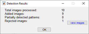
To view the rejected images, click view images. In addition to duplicate images, the calibrator also rejects images where it could not detect the entire pattern. Possible reasons for no detection are a blurry image or an extreme angle of the pattern. Detection takes longer for larger images and patterns that contain a large number of elements.
The Data Browser pane displays a list of images with their IDs. Each image contains a detected pattern. To view an image, select it from the Data Browser pane.

The Image pane displays the selected
checkerboard image with green circles overlaid to indicate detected points. You
can verify that the corners have been detected correctly by using the zoom
controls. The yellow square indicates the (0,0) origin. The
X and Y arrows indicate the
checkerboard axes orientation.
Calibrate
Once you are satisfied with the accepted images, on the Calibration tab, select Calibrate. The default calibration settings use a minimum set of camera parameters. Start by running the calibration with the default settings. After evaluating the results, you can try to improve calibration accuracy by adjusting the settings or adding or removing images, and then calibrating again. If you switch between the standard and fisheye camera models, you must recalibrate.
Evaluate Calibration Results
You can evaluate calibration accuracy by examining the reprojection errors, examining the camera extrinsics, or viewing the undistorted image. For best calibration results, use all three methods of evaluation.

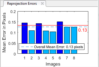
The reprojection errors are the distances, in pixels, between the detected and the corresponding reprojected points. The Camera Calibrator app calculates reprojection errors by projecting points from the world coordinates defined by the pattern into image coordinates. The app then compares the reprojected points to the corresponding detected points. As a general rule, mean reprojection errors of less than one pixel are acceptable.

The Camera Calibrator app displays, in pixels, the reprojection errors as a bar graph. The graph helps you identify which images adversely impact the calibration. You can select a bar graph entry to select an image, and then remove the image from the list of images in the Data Browser pane.
Reprojection Errors Bar
Graph
The bar graph displays the mean reprojection
error per image, along with the overall mean error. The bar labels correspond to
the image IDs. The highlighted bars correspond to the selected images.
Select an image in one of these ways:
Click a corresponding bar in the graph.
Select an image from the list of images in the Data Browser pane.
Adjust the overall mean error. Slide the red line up or down to automatically select all images with a mean error greater than the specified value.
The 3-D extrinsic parameters plot provides a camera-centric view of the patterns and a pattern-centric view of the camera. The camera-centric view is helpful if the camera is stationary when the images are captured. The pattern-centric view is helpful if the pattern is stationary. You can click and drag the figure to rotate it. Click a checkerboard (or camera) to select it. The highlighted data in the visualizations corresponds to the selected image in the list. Examine the relative positions of the pattern and the camera to determine if they match what you expect. For example, a pattern that appears behind the camera indicates a calibration error.

To view the effects of removing lens distortion, on the Calibration tab, in the View section, select Show Undistorted in the View section of the Calibration tab. If the calibration is accurate, the distorted lines in the image preview become straight.

Note
Checking the undistorted images is important even if the reprojection errors are low. For example, if the pattern covers only a small percentage of the image, the distortion estimation can be incorrect, even though the calibration resulted in few reprojection errors. This image shows an example of this type of incorrect estimation for a single camera calibration.
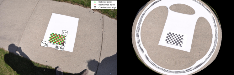
For the fisheye camera model, you can alternate between viewing the distorted and undistorted images by selecting Show Undistorted. While viewing the undistorted images, you can inspect the fisheye images more closely. On the Calibration tab, in the View section, adjust the Fisheye Scale. Enter a value in the Fisheye Scale field, or use the arrows to increase or decrease the scale.

Improve Calibration
To improve the calibration, you can remove high-error images, add more images, or modify the calibrator settings.
Consider adding more images if:
You have fewer than 10 images.
The calibration patterns do not cover enough of the image frame.
The calibration patterns do not have enough variation in orientation with respect to the camera.
Consider removing images if the images:
Have a high mean reprojection error.
Are blurry.
Contain a calibration pattern at an angle greater than 45 degrees relative to the camera plane.

Incorrectly detected calibration pattern points.
You can specify two or three radial distortion coefficients. On the Calibrations tab, in the Camera Model section, with Standard selected, click Options. Specify the Radial Distortion as either two or three coefficients by selecting 2 Coefficients or 3 Coefficients, respectively.
Radial distortion is the displacement of image points along radial lines extending from the principal point.
As image points move away from the principal point (positive radial displacement), image magnification decreases and a pincushion-shaped distortion occurs on the image.
As image points move toward the principal point (negative radial displacement), image magnification increases and a barrel-shaped distortion occurs on the image.

The radial distortion coefficients model this type of distortion. The distorted points are denoted as (xdistorted, ydistorted):
xdistorted = x(1 + k1*r2 + k2*r4 + k3*r6)
ydistorted= y(1 + k1*r2 + k2*r4 + k3*r6)
x, y — Undistorted pixel locations. x and y are in normalized image coordinates. Normalized image coordinates are calculated from pixel coordinates by translating to the optical center and dividing by the focal length in pixels. Thus, x and y are dimensionless.
k1, k2, and k3 — Radial distortion coefficients of the lens.
r2 = x2 + y2
Typically, two coefficients are sufficient for calibration. For severe distortion, such as in wide-angle lenses, you can select three coefficients to include k3.
The undistorted pixel locations are in normalized image coordinates, with the origin at the optical center. The coordinates are expressed in world units.
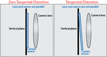
Tangential distortion occurs when the lens and the image plane are not parallel. The tangential distortion coefficients model this type of distortion.
The distorted points are denoted as (xdistorted, ydistorted):
xdistorted = x + [2 * p1 * x * y + p2 * (r2 + 2 * x2)]
ydistorted = y + [p1 * (r2 + 2 *y2) + 2 * p2 * x * y]
x, y — Undistorted pixel locations. x and y are in normalized image coordinates. Normalized image coordinates are calculated from pixel coordinates by translating to the optical center and dividing by the focal length in pixels. Thus, x and y are dimensionless.
p1 and p2 — Tangential distortion coefficients of the lens.
r2 = x2 + y2
To estimate the tangential distortion coefficients, on the Calibration tab, in the Camera Model section, select Options > Compute > Tangential Distortion. Otherwise, the calibrator sets the tangential distortion coefficients to zero.
Export Camera Parameters
When you are satisfied with your calibration accuracy, select Export Camera Parameters for a standard camera model or Export Camera Parameters for a fisheye camera model. You can either export the camera parameters to an object in the MATLAB workspace or generate the camera parameters as a MATLAB script. If the default values work well, then you do not need to make any adjustments before exporting the parameters
References
[1] Zhang, Z. “A Flexible New Technique for Camera Calibration.” IEEE Transactions on Pattern Analysis and Machine Intelligence. 22, no. 11 (November 2000): 1330–34. https://doi.org/10.1109/34.888718.
[2] Heikkila, J., and O. Silven. “A Four-step Camera Calibration Procedure with Implicit Image Correction.” In Proceedings of IEEE Computer Society Conference on Computer Vision and Pattern Recognition. 1106–12. San Juan, Puerto Rico: IEEE Comput. Soc, 1997. https://doi.org/10.1109/CVPR.1997.609468.
[3] Scaramuzza, Davide, Agostino Martinelli, and Roland Siegwart. "A Toolbox for Easily Calibrating Omnidirectional Cameras." In Proceedings of IEEE International Workshop on Intelligent Robots and Systems 2006 (IROS 2006), 5695–701. Beijing, China: IEEE, 2006. https://doi.org/10.1109/IROS.2006.282372
[4] Urban, Steffen, Jens Leitloff, and Stefan Hinz. “Improved Wide-Angle, Fisheye and Omnidirectional Camera Calibration.” ISPRS Journal of Photogrammetry and Remote Sensing 108 (October 2015): 72–79. https://doi.org/10.1016/j.isprsjprs.2015.06.005.
See Also
Apps
Functions
showReprojectionErrors|showExtrinsics|undistortImage|detectCheckerboardPoints|generateCheckerboardPoints|estimateCameraParameters|detectCharucoBoardPoints|detectAprilGridPoints
Objects
Topics
- Data Collection Guidelines for Single-Camera Calibration
- Select Calibration Pattern and Set Properties
- Evaluating the Accuracy of Single Camera Calibration
- Measuring Planar Objects with a Calibrated Camera
- Camera Calibration Using Custom Planar Calibration Patterns
- Structure from Motion from Two Views
- Structure from Motion from Multiple Views
- Depth Estimation from Stereo Video
- 3-D Point Cloud Registration and Stitching
- Uncalibrated Stereo Image Rectification
- Using the Stereo Camera Calibrator App
- Coordinate Systems
- Implement Visual SLAM in MATLAB
- Camera Calibration with MATLAB

