Introduction to Scheduling on C2000 MCUs | Getting Started with C2000 Microcontroller Blockset, Part 5
From the series: Getting Started with C2000 Microcontroller Blockset
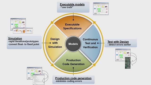
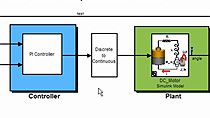
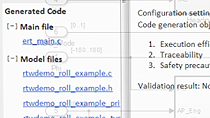
Learn the concept of information overlay and how the sample time configurations of blocks in any Simulink® model configured for C2000™ hardware define the rates at which the code is executed on C2000 MCUs using the code generated by Embedded Coder® and C2000 Microcontroller Blockset. See how the concept base rate uses constant blocks and GPIO blocks to control the onboard LEDs of an F28379D LaunchPad™. You’ll also learn how to run various signal chains in different rates on TI C2000 MCUs.
Published: 13 Jan 2025
In this video, we will look more into sample time and information overlays.
The first thing that you do after opening your blank Simulink model is to open the configuration parameters by pressing Control-E. Go to the Hardware Implementation tab. And select the board. In our case, it's going to be F28379D LaunchPad. Click on OK.
Once you have configured the model for your hardware board, you can start designing your model. So for simplicity, let me add a constant block and a digital output block of F28379D. Let me replicate this.
And let me open the block parameter of the first constant block. Let the Constant value be 1 and the Sample time be 0.1 and here the Constant value be 1 again and the Sample time be 0.2.
And coming to the digital output block, let me select the pin 31 and toggle it. And pin 31 is for the onboard LED. And here, let me select pin 34. GPIO pin 31 and 34 are for the onboard red and blue LED.
So I have designed a Simulink model to blink an onboard LEDs at a rate of 0.1 second and 0.2 second. Once having my model designed, the first thing that everyone should be doing is to go to this Sample Time icon over here and select the colors. You can see the model have become colorful.
But there are some color codings behind these colors. So if you'll see, on the right side of your Simulink window, you could see all the red color denotes the blocks that are running at a 0.1 second sample rate. And green color is for the blocks that are running at 0.2 sample rate. If I speak in terms of frequency, the 0.1 is 10 hertz. 0.2 is 5 hertz. So the fastest running block is of red color. And the next slower block is of green color.
If I have one more block that is running still slower than this, it would be of blue color. Let me check that. So if I have another constant block over here and say it is of 0.3, for now, let this be GPIOx. And let me update the model. You can do that by going to the Modeling tab and update the model. Or you can quickly do a Control-D.
You could see here, there is a blue color that is appearing. So the fastest is red. And the second fastest that is a bit slower than the red color blocks are in green. And the third fastest is in blue. So these are the color notations.
So whenever you design your model, make sure that you have some red blocks on it and some blocks on other sample rate. You could see the different sample rates that are available in the model over here-- so 0.1, 0.2, 0.3. So how the scheduling happens in the microcontroller is that it takes the least common multiple of all the three values. That is 0.1, 2, and 3. And the least common multiple would be 0.1. That is 10 hertz.
So the microcontroller runs the model at this 10-hertz rate. And this 10 hertz is called as the base rate, which is the least common multiple of all the sample rates that are available on your model. If you don't have any blocks that are running at this base rate, then you will simply make the microcontroller to run at a faster rate without doing any task at that particular speed. And that can sometimes crash your microcontroller by unnecessarily make the microcontroller to run at that particular rate. So always make sure you have that sample time in control.
Say, for example, if I have a sample time of 0.133 and here a sample time of 0.23 and here a sample time of 0.3 and do a quick update, here, you could see there isn't any red blocks available on this model. It means that I am running the microcontroller at a different base rate. But at that base rate, I am not having any particular task.
So to not necessarily kill the microcontroller by running at that higher rate, make sure that you change your model accordingly so that it has some blocks that are running on the base rate. That's all about the information overlays. Click on the Sample Time icon over here, and select the colors. You can also do that by going to the Debugging tab and clicking on the Information Overlay. You could see the colors has been enabled. You can also enable it from here.
This is all about the feature information overlay that is available in Simulink. Thank you for watching the video.