Mars Sample Fetch Rover: Autonomous, Robotic Sample Fetching
Raul Arribas, Airbus Defence and Space
As part of the Mars Sample Return (ESA-NASA) mission, Airbus Defence and Space UK is developing the Mars Sample Fetch Rover. The rover's role is to autonomously drive and pick up samples left by the Perseverance rover on the Mars surface. This presentation will focus on the robotics at the front of the rover (camera systems and robotic arm) that are used to identify, grasp, and stow these samples (without human in the loop). This system is designed in MATLAB® and Simulink® and then translated into C code for flight software using the autocode packages.
Published: 28 May 2022
[MUSIC PLAYING]
Hello, I'm Raul Arribas. And I work at Airbus in robotics and mission performance for the Mars Sample Fetch Rover. I think this is a really cool project, and maybe one of the most daring challenges in robotic space flight. So I'm happy to talk a bit about the work we're doing here.
So what I've done is divide the presentation into three parts. First we'll go through an overview of the Mars Sample Fetch Rover and Mars Sample Return mission for some context. And we'll see, from this overall context, why high autonomy and fast development are two key themes. So the second and third part of this presentation will be looking at these two themes and how they impact directly my most immediate theme.
So starting off with that mission overview, this is the most high level diagram of how the mission architecture works. The first thing to understand in the Mars Sample Return campaign is it's a fairly sort of complex, inter-agency, multi-mission campaign. So it involves both NASA and ESA, which are the American and European Space agencies. And it's happening throughout this entire decade.
There's three major launches that are currently foreseen. So the first one is the Mars 2020 Perseverance. This is a NASA mission with a NASA Rover that collects samples and leaves them on the surface. You've most likely seen this already in the news with the helicopter flying around Mars.
On the second mission, which is the one that my team is working on, this is expected in 2028. This is the Sample Retrieval Lander-- sorry, the Sample Fetch Rover that the European Space Agency is heavily involved in. The third part of the mission, which is around 2028, is not a rover like the first two, but a spacecraft from the European Space Agency which orbits around Mars and collects the samples.
It then returns these samples to Earth with a NASA entry capsule. So this is a fairly complicated diagram. So it just kind of go over it again in images, so it's a bit easier to explain. But the first part of the mission is, like I mentioned, already underway. This is the Perseverance Rover that is collecting samples.
So what happens here is that scientists on Earth will decide what the most interesting geological features on the Mars surface are worth investigating and exploring. So this rover can drill things on the surface and collect this into tubes. And it'll leave these tubes scattered throughout the surface of Mars over many years.
Then the second part of the mission which is the part I'm working on, is the Sample Fetch Rover. Now, this will drive quite long distances and collect the samples that the Perseverance has been leaving behind. It will then go to-- it will return these samples to a launch pad, where the samples are then launched from our surface up into Mars orbit.
And here, the samples are left in a parking orbit, where the third part of the mission, the European spacecraft Earth Return Orbiter, comes into Mars orbit and collects these samples. It then takes the samples and returns them back to the Earth, where the samples crash land and are recovered for scientific study.
So that's the big overview of all the different components of the mission. It's important to understand in this big picture the constraints and challenges with all of this involved. We're doing several transits from Earth to Mars and from Mars back to Earth. However, this isn't a simple journey to take.
Because of the planetary motion, we need a very specific alignment of the planets, Earth and Mars, in order to be able to travel from one to the other. So these set very strict start and end dates to the mission. There's not much we can do about. It's orbital mechanics.
And this means that there's a certain time pressure for the work that we're doing on Mars, because we have a very specific date we need to leave at. Perseverance has already started this campaign. It's already on Mars. It's already picking up samples. So the timer is ticking. And whether we like it or not, this mission is going forward.
So this has two major implications. So the first one is on the flight operations. We have a very limited time on the surface of Mars. The Earth-Mars communication takes a very long time because of the speed of light. And these two facts mean that we need a very high level of autonomy on the surface of Mars.
The rover must act independently of the human owner. They cannot be remote controlled, so to speak. It must behave independently. So that this can keep the pace it needs on Mars. The second major takeaway is the mission development. So we have a very clear launch date that we need to hit. And we need to design, verify, and test a completely bespoke rover in this amount of time. So this requires very fast development from now until then.
So that is the overview of the mission and the high level of autonomy and the fast development that sort of comes from the natural constraints and the mission design. So what we'll do next is kind of go into these in a bit more detail. So the high autonomy that the rover has impacts all aspects of the rover. In particular, and the team that I'm focused on, is the pickup of the samples on the surface of Mars.
So this is the sequence that is divided into three major steps. First of all, we need to find where the samples are on the surface. And for this, we have a detection part of the sequence. Here, the camera system will take images of the ground and run it through a visual based detection system, which is a machine learning algorithm. And this helps identify the samples, where they are in 3D space, as well as their orientation relative to the rover.
These algorithms also generate a point cloud that defines the terrain around the sample. And this is generated to ensure that we avoid any major obstacles around the sample. The second part is the grasping. So here, the robotic arm is controlled to pick up the sample, to avoid obstacles and train. And we can check whether this has been successful with a visual check as well.
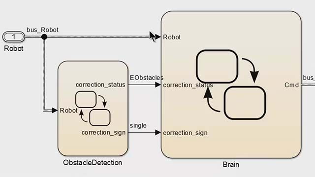
The final part of the sequence is what we call the stow. And here, we manipulate the sample to bring it on board as the final step, which is fairly delicate. Now, the sequence is developed entirely in MATLAB Simulink environment using two major toolboxes, the Robotic and the Statistics Toolbox. And what I've done here on the right hand side is drawn a sort of high level view of the algorithm, how it works.
And as you can see, divided into three parts, I kind of color coded them. So that the first one, yellow here, being the state machine that has a status of the equipment and executes transitions between the modes. The second part is the asynchronous processor here in green, where any complex computation can be offloaded to it. And then the third part is sort of an orange below it, the ARM, the gripper robotics, the camera. These are all equipment at the front of the rover that interact with the sample and the terrain in front of the rover.
So to understand how this algorithm here works at a high level, we could sort of run through an example. Where the state machine, for example, at a certain stage of the operation, decides to attempt to detect where a sample is. So what it'll do is request the camera to take an image.
Once the camera has processed the image, it will send it to the asynchronous processor, where fairly computationally expensive algorithms are run to detect the position of the sample, detect its orientation in 3D space, to generate a point cloud of the terrain data around the sample. All this information is run asynchronously and then sort of summarized and given back to the state machine.
Then, the state machine could, based off of this information, then decide to manipulate the arm to pick up the sample and send the commands to the telecommand and telemetry manager for the arm. And this would interact with the arm here that would, for example, pick up the sample and move it on board the rover. So it can then interact mechanically with interfaces at the front of the rover.
And this whole algorithm is designed within MATLAB Simulink environment. And at this stage of design, is fairly high level. But we can see in the next few slides how we intend to develop this into flight software. So this sort of leads us on to the next point, which is the fast development, and how we're going from the early stage preliminary design of something all the way to the flight software as quickly as possible.
So for context, something that Airbus has been developing for quite some time now is autocoding or code generation. And here, the objective is to optimize our process by taking advantage as much as possible of the MATLAB Simulink tools and environment, as well as keeping, by default, a series of compliances to ECSS standards which are important in the aerospace industry.
So the solution we've devised and we've been working on for quite some time now is this code generation approach using coders within the MATLAB Simulink environment that can automatically generate documentation as well as C code and many other documents. So Airbus has quite a heritage here developing autocoding systems for quite some time now.
OneWeb, for example, is a constellation of satellites currently in orbit. That was the first autocoded control system that Airbus developed in flight and then tested in flight. Many software modes or states of the satellites were coded up with this autocoding process. And all of these modes have been run in flight and they've behaved as expected while in flight. So yeah, it's been-- not just like-- this isn't just a theoretical method that Airbus is currently developing.
But it's something that is already in flight, and tested, and has been shown to deliver good behavior and delivered on time while ensuring compliance to all of these standards that are shown here on these slides. So the way this works is the MCL, which is essentially the algorithm that controls all the flight dynamics here at the bottom of the screen, is developed within MATLAB.
And this is what the control engineers work on. But this can be embedded into two different things here. So on the left hand side, the simulation environment. And then on the right hand side, the autocoding factory. Here in the simulation environment, we try to replicate what would physically occur to the system during a mission.
Many simulations are run. Many different environments and cases, where we can see the performance of the control system under these different scenarios. And then the second part, on the right hand side, is the autocoding factory. So this generates the documentation, all the reports, all the checks, as well as the C code that can be run directly on the flight computer.
So just effectively what we can do here is with this single source, this MATLAB simulation model that we have here on the bottom left hand side of the screen, here we-- the guidance, navigation, and control team can work on a MATLAB model that then, here, we have all the high level algorithms that are being developed, but can be the single source to automatically generate all the C code and documentation needed for all of these other teams.
So from the same source, we can send information to the simulations team, the software team, the fault detection team. And all of this is used to generate the flight computer for any satellite or any system in Airbus space. So this means that the link between the original algorithm here on the left hand side of the screen and the flight software all the way on the right hand side of the screen can be done much more quickly and automatically.
This reduces human error in this process, as well as the number of hours required to take this from a preliminary concept to the final version. So this is the brief overview of how we're using MATLAB and all of its tools and generations specifically in this Mars Sample Fetch Rover project to take those preliminary algorithms all the way to the flight software this will be using.
So to recap, we've gone quite quickly over these things here. But we saw an overview of the mission and the return of samples from Mars. We saw the very strict time constraints that we had, from the orbital mechanics that motivate and produce this high level of autonomy in all the rovers and systems.
So we went through, for example, the fetching part of the sequence, where we divided things into three parts. And we saw that the algorithm was entirely self-sufficient and relied on things like machine learning and fairly complex algorithms it had on board to make its own decisions and be able to perform tasks without humans in the loop.
The last stage of this presentation, we saw how fast development was also a key thing in this project, that we've been developing algorithms in MATLAB that can automate the generation of the flight software, and all of the documentation that we need from the original source, MATLAB scripts that were done in the preliminary design.
And yeah, I think that wraps up the whole presentation. And it's a really exciting project that we'll be working on the next few years and really looking forward to sharing how we progress that going forward. Thank you very much.