Space Industry Safety Regulation and Software Engineering Standards - MATLAB
Video Player is loading.
Current Time 0:00
Duration 43:46
Loaded: 0.38%
Stream Type LIVE
Remaining Time 43:46
 
1x
  • Chapters
  • descriptions off, selected
  • captions off, selected
  • en (Main), selected
    Video length is 43:46

    Space Industry Safety Regulation and Software Engineering Standards

    Lewis McCluskey, Southern Launch
    Nathan Drummond, Southern Launch

    Overview

    Safety and risk management are paramount considerations for companies developing systems for launch vehicles and space craft. Not only for ensuring a safe launch and return, but also to comply with certifications in line with engineering standards, such as NPR 7150.2 (NASA-Software Engineering Requirements) and ECSS-E-ST-40C (ECSS-Software Engineering).

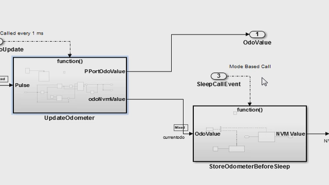
    This presentation provides an overview of applying Model-Based Design to develop space software based on space software engineering standards, as well as a case study from Australian start-up Southern Launch, who have developed Rocket Flight Safety Analysis tools and Space System applications using built-in MATLAB functionality. The goal of this presentation is to provide sufficient background of the overall process, starting from requirements and following the development process all the way through verification of the object code on a target processor.

    Highlights

    • Learn the overall development process of software development in the context of space software engineering standards.
    • Discover how Model-Based Design enables space software development from to verification of the object code on a target processor from a case study.
    • Hear how Southern Launch developed their Rocket Flight Safety Analysis Tool to assess danger areas, compute the expected number of casualties, and generate exclusion zones for a launch.

    About the Presenters

    Lewis McCluskey is a senior launch engineer at Southern Launch and has led the development of Southern Launch’s rocket range safety analysis process.  Lewis works alongside some of the largest rocket manufacturers in the world to understand how their rockets could be safely launched in Australia. He has developed a strong understanding of rocket technologies, and how safe rocket launches can be carried out. Lewis studied Aerospace Engineering at the University of Adelaide, graduating in 2019.

    Nathan Drummond graduated with a degree in aerospace engineering and business management in 2021 from RMIT University, Melbourne. Nathan gained practical experience in rocket design in his role as the aerostructural team lead of a university rocketry club that competed in 2019 Australian Universities Rocket Competition (AURC). Nathan led the winning team that successfully launched a sounding rocket with a scientific payload onboard to 30,000 ft and recovered it intact. To further adapt his skills, Nathan spent time abroad in Germany, where he gained experience as a thermal engineer working on the Ariane series of launch vehicles. Nathan has since joined the Southern Launch team in his role as a Launch Engineer and has a keen interest to develop and shape the future of Australian Space launch.

    Alex Shin is a Principal Application Engineer at MathWorks. He specialises in helping customers in the area of simulation, verification and automatic code generation, primarily for commercial projects. His recent work includes defining simulation and verification process and implementation of Model-Based Design tools in large organisations. Mr. Shin received Bachelor’s degree from University of New South Wales in mechatronics engineering.

    Recorded: 30 Mar 2022

    All right, thank you, Ian, for that introduction. Oh, sorry, guys. So thank you all for joining us for our talk today on Space Industry Safety Regulation and Software Engineering Standards. So I'm Lewis, and this is Nathan.

    Hello.

    So we'll be talking a bit about how we use MathWorks products to assist with the space regulation, as outlined by Ian earlier. And we'll also give a brief introduction to our company and of space market which Nathan will lead with straight away.

    Thanks, Lewis, and thank you again for inviting me today. So as Lewis said, just before we get into what we're really here for today, I'm just going to go a bit over the space market current industry and where Southern Launch fits in. So gone are the days, I guess, where companies, satellite developers are reliant on those heavy launch capabilities-- so your typical heavy launches that cost millions upon millions and have extensively large lead times to get technologies up into space.

    So what we've seen recently is a transition to what we're calling new space technology. So that's because of companies now being able to develop technologies with much more form factors. We're able to develop satellites and launch satellites into space much quicker and much more cheaply as well. So this is where Southern Launch is trying to enter the market and really provide a range of different service offerings.

    So here, I've got the five key service pillars that Southern Launch is offering at Southern Launch, so the being our orbital launch capability. So we own and operate a launch site that gives access to orbital launches over a whole different range of inclinations-- so polar, sun-synchronous-- to test many different rocket systems and payloads.

    We also have a suborbital launch site, which is extremely handy for safely testing and recovering rocket devices. So that's another whole range of services we can provide to customers. And more so on my role, and Lewis's role as well, is actually the mission and campaign design. So this is where we use all our MathWorks software tools to really provide us with the most amount of surveillance on range. On top of that, we also have rocket design and hardware avionics consulting, as well as security technology transfer, helping with the launch licensing process and the insurances-- so all the regulatory matters that go along with the launch.

    So just quickly, our two launch sites. This is our orbital launch complex. So it's located in Whaler's Way, which is just outside of Port Lincoln.

    So it's a very remote area, which is extremely beneficial, because it's away for most civilization so we don't have to worry about posing risk to any inhabitants that live close by and because we have unhindered access out into the ocean [AUDIO OUT] minimize, I guess, the effect on air traffic, as well as marine traffic. So again, it gives us a whole wide different range of orbits we can achieve.

    And on the Koonibba Test Range, our suborbital range, we've got about 145 kilometers down-range, so a lot of space for customers to test their upcoming technologies, their rocket systems, and there is potential also to further extend that downrange as well. So it's pretty exciting moving forward with that on the horizon.

    So that's just a bit of an overview of, I guess, where we are in the industry, as well as Southern Launch. So now what we're really here for is space regulation using MathWorks products. So I'll hand over to Lewis to get into that.

    Obviously, Ian touched on this a little bit earlier in the talk, and I wanted to go into it in a little more detail, just to provide context for what's about to come. But launch in Australia is really regulated into two categories-- one called space and non-space. So anything below 100 kilometers, where the von Kármán line, that is regulated by the Civil Aviation Safety Authority. Everything for the context of what we're providing for today will be with the Australian Space Agency, which is above 100 kilometers, or it meets another set of criteria for high-powered rockets, which we won't get into. But it's all governed by that Space Launches and Returns Act 2018, which again, Ian, presented a little bit earlier.

    So for us, as a launch service provider, we require the approvals to get more facility licenses and an Australian launch permit or a high-powered rocket permit. But to do so, we need to be able to demonstrate that the risk meets the launch safety standards. So those standards are born from the Flight Safety Code, which is really a methodology that the space agency has put out that we, the launch service provider either work with a suitably qualified expert to perform these assessments, depending on the type of launch, or we perform this assessment ourselves. And to do so we've created tools using MathWorks products that allow us to do that.

    So the flight safety approach, this is a quantitative methodology, and we're getting into some of the terminology a little bit later. But essentially it allows us to really identify potential hazards during the launch and return that might cause harm to public health and safety, analyze, the risks associated with those hazards, and then develop measures to minimize those risks and ensure they remain below those particular established safety standards.

    So some key aspects, because we'll probably use these terminologies a little bit throughout the remainder of this presentation. So the first one is that drop zones. So a drop zone is a scheduled area that the 3-sigma ellipse contains all foreseeable normal impacts from a Monte Carlo simulation. Failure response mode is the other aspect of flight safety. So we do the assessment for different scenarios that we can see, which would be resulting in a successful mission.

    And then we also assess what would happen if the vehicle fails. And a typical failure response mode can have a set of values that result in a determinable vehicle response. Usually, it's one of a few. There are only really a few ways that a vehicle can respond. And we'll come to some examples of that later on.

    The other one we have here is a casualty area. This is an area of debris where a person would become a casualty. And essentially what the image on the right is showing-- that's from the FAA's high fidelity flight safety analysis.

    And it's really demonstrating the size of the debris, which could cause a casualty of some person. And there's a whole bunch of factors that come into that outside of its size, the angle of impact there for a direct hit, whether or not you would have-- you can see that indirect hit forms a crater and it ejects some more debris or if it splatters and then rolls or bounces. all of those factors are quantify what's known as the casualty area.

    Then moving forward this, we have probability of impact. So this is really-- the simple one is just the impact probability per area size. Typically square meters is what we use. We have another risk criteria called an individual risk. It's the risk that a person standing on the open, like in the image there, would become a casualty due to a launch. And the associated safety standard with that is it must be a less than 1 in a million, or 1 to the minus 6.

    And the last one on there is the expected casualties. So we're taken to account population data, assess where everybody is in relation to the launch, and then calculate how many people we would expect to become a casualty. Obviously none, but the launch criteria as specified by the space agency's rules is it must be less than 1 in 1,000.

    So that's the problem framework that we're trying to solve here. And to do so, we have a life cycle here, which is for what we'll talk mostly about today, which is [AUDIO OUT] be developed which we've called MAGIC. And again, this is using, obviously, MathWorks products.

    So when we came up with the concept of MAGIC, we first, obviously, set the traditional lifecycle of our flight safety assessment. So that was preparing the geospatial data, modeling the vehicle. And that includes making sure that we have aerodynamics, propulsion, structures, gravimetrics, GNC, the flight termination systems, et cetera. And we take into account all of those details and we build a model for it.

    So for our launch safety, the simulation tool we use for this is known as ASTOS, and that builds our model for us. We then created MAGIC, which is the software piece in MathWorks which then wraps around ASTOS and then performs the failure trajectories, nominal trajectories, all sorts of dispersion trajectories from there afterwards, and then coordinates with the ASTOS tool to be able to generate the results for the impact locations, collate them afterwards, and then process them through what we've called there the PDF pipeline, or really casualty risk safety pipeline, which performs all the complex calculations to meet the parameters that I showed in the previous slide before and to ultimately create the results that we're looking for to make sure that our launch is within those safety standards.

    So this is a typical workflow, on the right, for MAGIC. And on the left, we have an example isometric view of rocket launch trajectory. In this particular example, it's a two-stage one. And this one has a subset of FRM. So this one here, we're really just looking at three FRMs.

    So I'll just briefly go over it. So you're seeing, in green, at the very base of the Koonibba test range, those dots are the result of an explosion failure response mode for this particular vehicle. The yellow dots north of that are actually the results of a stage-one successfully landing.

    The purple dots are a stage-two explosion, mid-flight. So there's a space in this particular trajectory here, and then the second stage ignites. And at the far end, the most northern point there in that image, are our dispersed stage-two landings. And obviously the red is the trajectory that that would fly under a nominal no-wind scenario.

    So when we operate MAGIC, we developed it using an object-orientated approach. And so we structured it in a way that matched the lifecycle process. So we started off by creating the object, which then defines the Monte Carlo parameters and analyzes it.

    We then perform the Monte Carlo analysis, and the results are shown there on the left. We do a convergence assessment, and we'll show that later on. And then we collate the results using that pipeline that we spoke about, where we collect the GIPs, and we just have all of the different parameters there. It's radius, ballistic coefficients, and it's safety factors for a splatter or roll, which then correlates to the casualty area, which then relates to the failure response mode which maybe it was given by too. It Calculates. The probability distribution function of impact, the individual risk, and that then forms a subset of failure response mode that gives the ultimate range safety highest-level object, which then performs the expected casualty calculations, taking into account the population data, and then really develops all of the maps and the overall range safety template.

    To give more of an image of what the range safety template could look like, for example, here's another example. So this is for a small sounding rocket. And this one here shows two failure response modes, similar to the last one, in a nominal landing and explosion during boost.

    And when I spoke about the isopleths before, the risk isopleths, this is really what we mean. Here you have of a constant probability drawn over a particular area. And this one here is showing the individual risk.

    And as per the safety standards, there should be no populations within that "one in a million" individual risk, which is the red line there. So what we do is we take into account all of that data generated probability of impact and individual risk to meet the launch safety criteria, take into account the populations, which you can see faintly marked on there, and then calculate the expected casualties and calculate those areas of risk.

    So one of the questions that we have to answer when we do our launch safety assessment is, how many simulations are enough? Obviously, we did just a couple or three, and you can't say we're done there. There needs to be a sufficient amount, but how much is really the question.

    So we've developed, using information theory, a convergence assessment, which is what I'm playing on the right there for you, which shows the isopleths developing for a set of GIPs. So in this scenario here, there has been 34,000 simulations. And then we assess what's called the KL divergence, which, again, that's a subset of information theory, to look at how much information is changing inside of that probability distribution function and ensure that it's not changing by a sufficient amount, which we have a criteria here 10 to the minus 3 in overall percent change of information, which really links to the isopleths there. And then how much probability it is changing or how much is left in that solution space. And once it reaches that criteria, that's when we assess it's converged.

    So that's our convergence analysis there. Now we're going to tie it to a software standard. So obviously, you can imagine the criticality of MAGIC being used to assess the launch safety standards-- being used to meet those rather. And we need to ensure that it's been done correctly and verified, and the verification methodology that we used for that.

    One such example here that we pulled out is the IEEE 29148. They're obviously space-related standards that will be discussed later on today. But this one here, we're just highlighting this particular standard. And so we developed a software assurance process based on international standards that describe requirements for engineering processes and for the development of the software.

    So to be able to actually verify the requirements of the software, there's usually four typical methodologies for verification of requirements. So we're looking at inspection, demonstration, tests, and analysis. This links to our MAGIC software that we built, and we're really looking at the object-oriented code that we're trying to test here and make sure that it meets the requirements to perform a flight safety analysis.

    So the four key areas that we're looking at is inspection, such as visual examination. So an example of a GUI, buttons there for functionality, which we used for the simple screenshots. For demonstration, we're looking at interacting with the product to elicit a particular response. So given some parameters, we expect to see this. How we perform that using MathWorks products is just scripts that automatically save images and code for demonstration tests, for example.

    There's the test verification. So this is a set of inputs that result in a determinable answer. And we have automated generated pass/fail reports for that.

    And then lastly, there's the analysis approach. That's verification of it by reference to model scale-ups or rather some external data source. And once again, we used the inbuilt test framework inside of MathWorks products to evaluate against analysis criteria for the pass/fail given a particular criteria for verification.

    And the images I have in here are little extracts that I pulled out which show the MATLAB automatic generated test report. So in this particular one, we performed 24 tests. And then, overall, they passed. Typically, obviously, in software development, as we were running it through, we make a change to a particular subset or some code.

    We can see when these fail, which makes this really handy for rapid development for us, because we can run it through, make an adjustment, run it through the test framework, and then if we see a criteria has failed, we can go through and update that and then make sure that it's OK.

    Then we have a code coverage report there, or at least the title of it, which we've also taken out here, extracted, at the bottom of this presentation slide, which again just shows how many lines do you have that are executable, and how many did you hit, and what's your overall coverage.

    So we've highlighted just one very quick example here of a verification method. This one's demonstration. So the requirement of the Space Agency is that MAGIC is capable of calculating the drop zones, which is the three sigma standard footprint, which is based on a distribution of [AUDIO OUT].

    So the image on the right shows the dispersion from all failure response modes. You can barely see it, but the green dots on there are the nominal responses in this particular example. And on the left we've extracted out an isolated line, the 3-sigma drop zone, which is highlighted with the white dashed line. That's it for us. Thank you for listening.

    Yeah, thanks, Lewis and Nathan. Thank you very much for the presentation. We've got a little bit of time left with both Lewis and--

    Welcome to the session. When developing software for space systems, such as launch vehicles and satellites, companies usually follow space industry software engineering standards. In this session, we would like to present how model-based design can be used to develop software for space systems following these standards. Hello, everyone. My name is Alex Shin, a principal application engineer at MathWorks.

    To launch vehicles in Australia, it is expected that you follow Australian space rules 2019 for launches and returns. The 2019 version is the latest at the time of this presentation. Section 48 outlines the required information on the launch vehicle, and part of that includes guidelines for software development.

    You need to provide a description of the development, qualification, and acceptance programs for software of these systems. They're also expected to provide information on functional testing, modeling, and analysis conducted on the software development. Last but not least is that you are also expected to provide results of the qualification verification.

    So to comply with the guidelines, space companies are referencing software development standards from NASA and European Space Agency. The rigor of the process will vary widely based on the space system that you are developing. A launch vehicle and a CubeSat will have different requirements. Companies also have internal standards often based on the aforementioned standards, as well as DO-178C which is a rigorous software development standard for the commercial avionics industry.

    Now let's take a look at NASA's soft engineering standard. According to the standard, software requirements phase is the most critical phase of development. It is important to have well-structured and rigorous requirements. Requirements provide the foundation for the entire software development lifecycle.

    The standard also outlines requirements for software testing. The functional testing should be verified against the software requirements. You're also expected to have a systematic approach on finding design defects. Use of accredited software models, simulations, and analysis tools are expected to be used for software development. There are additional standards outlining the use of models and simulations, such as NASA Standard 7009.

    The last part I would like to bring to your attention is the bi-directional traceability. Depending on the space system you are developing, you are expected to have a full bi-directional traceability from your requirements, software design, actual code, and test cases. At MathWorks, we provide an example workflow on how model-based design is mapped to NASA's software development standard. We call model-based design a systemic use of models throughout the development process. If you are interested to know more, please check the first presentation of this space webinar series.

    The mapping of model-based design and NASA's standard is based on our experience working with NASA, and the workflow has also been reviewed by NASA engineers. Model-based design mapping to European Space Agency standard is also available. Many programs in Europe have also used model-based design for their software development.

    Now I'd like to walk you through an example of software development workflow using model-based design. This is the model-based design workflow I'll be using to explain how software can be developed based on the space software engineering standards. The development should start with software requirements elicitation, which should be derived from the system-level requirements.

    Requirements typically come from Word, Excel, or more structured environments in requirements management tools like those. The engineers implements these informal ideas into model-based designs. This is challenging to get right when data is viewed and managed in separate tools. It is difficult to establish traceability between requirements and design.

    To work with requirements directly in Simulink, there is an important operation for Word, Excel, DOORS, and support for the standard requirements interchange format ReqIF. ReqIF is supported by most requirements management tools. If requirements change at the source, then an update operation synchronizes the changes.

    The Simulink user may want to edit the requirements or add more details, such as custom attributes, to the requirements. Additionally, through imported requirements, you can also create requirements where Simulink is the source of the requirement. To bring this and round-trip changes to external requirements tools, the ability to export requirements via ReqIF is available.

    With the requirements imported, you can now work with them while in Simulink. From the model, I entered the requirements perspective from the control on the lower right. A browser appears at the bottom showing your summary of the requirements.

    Property Inspector on the right shows all the details. To create a link, simply drag and drop the requirement. On the diagram, a badge shows where the link exists. I can optionally annotate the diagram with a description.

    Now you see that this requirement has a link to the block in the links pane and implementation. If I select a requirement, then the linked blocks are highlighted in the canvas. If I move lower to select another requirement, and then select the block, the link requirement is brought into the view in the browser to show you the link requirements. That was an example on how requirements can be imported, hosted, managed, and traced in the model-based design environment.

    Now let's move to verification and testing steps. You can start by checking the conformance of your models against modeling guidelines. There are a number of popular modeling guidelines you can find at our page. NASA has also shared the Orion GN&C modeling guidelines they have been using for their project. The guideline focuses on areas such as readability, development workflow, performance, and finding defects.

    Here is an example of a modeling guideline. The guideline talks about correct and incorrect ways of using Simulink models. You can automate manual review steps by running a tool called Model Advisor on your model. The results can be published in comprehensive reports to document the analysis results for design reviews or to keep as a record for audit purposes. Links are included to take you to the location of issues in the model.

    Recommended actions are included with the results for guidance on the next steps to fix the issue. This is particularly helpful for new users. For some checks, there's even an operation to automatically correct the issue.

    We also have dashboard. This shows the overall quality of the model. You can see some greens, blues, and oranges.

    Blue indicates informational data. Green shows the good part of the model. Orange identifies issues.

    Let's take a quick look at some of the metrics data available here. On the top right, you will see some statistics of your system to give you a general sense of how big your model is. Some of you are already using this kind of data for estimating resourcing needs or verification costs. By checking your model against industry standard modeling guidelines, you can efficiently improve the quality of your model.

    Now let's talk about requirements-based functional testing. So the model needs to be tested against its requirements. To do this, test cases are derived from the requirements, and we will need to test the models against the test cases. After the test, test reports should also be generated as the evidence for the testing.

    Simulink gives you a systematic way to test your models. First, you can isolate a component to test using test harnesses. This allows you to create a test environment without changing the original model. Then you can also test inputs in many different ways, including MAT files, Excel files, Signal Editor block, and Test Sequence blocks.

    To assess the simulation results, you can compare against baseline results that are saved into MAT or Excel files. You can write custom criteria using MATLAB code that is based on the MATLAB unit test framework, or you can use the test assessment block to define pass-fail conditions during simulation.

    You can also test your models in different modes, including Software-in-the-Loop, Processor-in-the-Loop, and Hardware-in-the-Loop. For scalability, you can run your tests in parallel by fully utilizing multiple codes that you have on your computer.

    In this example, I'd like to show you one workflow where we'll use results to generate a baseline test. This is a test in which the current simulation results are compared to expected results. This is an example of a closed-loop model with a fuel rate controller in a plant. Our goal is to unit test the fuel rate control block in isolation.

    By using the closed-loop model, we can record the inputs and outputs of the component and the test, and use it as a baseline or expected results. You can also do this manually or using APIs. And in this example, I'd like to show you how easy it is to use the widget available in Task Manager.

    First under APPS, I choose Simulink Test and launch the Test Manager app. And under New, add AUTO CREATE, I choose the result you test for model component.

    Now I'll specify the component and the test. I choose the model and the component that I want to test and click Next. In the first step, I need to set the test inputs. I would like to use the simulation of the closed-loop top model to record the input of the component and the test. So I choose the first option here.

    In the second step, I need to specify the verification strategy. I would like to use the simulation of the closed-loop top model to record the outputs of the component and the test. So I choose the first option here.

    In this last step, I need to specify the format for my input and output information to be recorded. I shall go ahead with Excel. I can also choose my file. I'll also specify the location of my test file. I replaced the existing Excel file.

    Now the top model is simulated, and the inputs and outputs of the controller are being recorded in the Excel file. A test harness is auto-generated. In the test case, it added to Test Manager. Let's explore this test case.

    You can see the inputs have been automatically configured from the Excel file, and so has the baseline. Let's quickly have a look at the Excel file. Now, as we can see, the inputs have been set up in these columns, and the output in these columns. Notice how the single metadata information, such as the data type, interpolation, and everything else has been automatically added from the model.

    So now when I run the test, the latest values from the Excel files are fetched and applied to the inputs and baseline. And now I can see that my test has passed. There was one workflow using the results. There are others. You can use Design Verifier, for example, to automatically generate the test cases.

    The Test Manager is available to help you manage and run your tests for simulation, baseline, or equivalent testing. You can visualize the results and debug any failures. You can group the tests into test suites and run single tests, single suites, or all the tests.

    While executing requirements-based testing, it's important to measure test completeness. When running tests, you can measure coverage to identify which parts of your model and generated code are exercised during testing. Coverage of results are highlighted on the Simulink Stateflow, C, S-functions, and MATLAB functions in the design. You can use missing coverage data to find gaps in testing, listing requirements, unintended functionality, or dead logic.

    You can also perform coverage analysis for C and C++ code generated from embedded code using soft in the loop and process in the loop simulations to identify untested portions of the generated code prior to software integration testing. Detailed coverage reports are produced with navigation back to the model.

    A large set of industry standard coverage metrics are available, such as MC/DC coverage, relational boundary coverage, and lot more. As you saw, Simulink provides a requirement-based testing framework that helps you quickly create test cases and verify your design, while also collecting coverage metrics.

    Now let's move to the next stage of the development process, automatic code generation. In the context of following the space standards, it's important that the generated code is traceable and also complies with coding rules such as MISRA C. We have a unified code generation technology that takes input from your multiple languages. And we generate C, C++, HDL, PLC, as well as GPU code.

    A key difference from classic development is that high-performance, production-ready embedded code is automatically generated from the model. It's important to note that many space system projects are actively using code generation as their final software. This completely eliminates coding time and pure coding mistakes, and improves the overall development time. It allows a team to do small, fast iterations between design and verification.

    Now let's look at a code generation example. This is a Simulink model that contains the state machine with transitions. By going to C CODE Toolstrip, you can press Generate Code button and the model is configured to automatically generate C code.

    Once the code generation is complete, we'll see a code generation report with the model. That's fully traceable. When I press the line of the code, it will highlight the portion of the model that maps to the generated code.

    And if I press the model, it will show you the code that's generated from that particular part of the model. So as you can see, the model and the generated code is fully traceable. Once the code is generated, you can check the generated code against popular coding standards, such as MISRA C, and also runs steady analysis to find any defects.

    Polyspace static code analysis supports the full range of static checks. This ranges from code matrix standards to bug finding to code proving. These tools can produce code reports on metrics such as cyclomatic complexity or MISRA code standards.

    Polyspace Bug Finder can also actively look for bugs on the code by checking the data and control flow of the software. These two can also check your code for security vulnerabilities and standards. Polyspace Code Prover uses formal methods to prove that your software is free of critical runtime errors.

    The graphics on the right show the code proving results overlaid on the source code. The code colored in green indicates that the court is proven to be free of critical runtime errors, whereas red indicates their presence.

    The model-based design framework also allows you to check the equivalence between simulation and generated code, and this is called equivalence testing. With software in the loop testing, you start with the test vectors used for the simulation. We then performed a desktop simulation with these test vectors and got other results. Using an embedded coder, you can generate code and compile the code for the desktop PC. This code is executed on the PC to produce results.

    The results for code execution are compared to the simulation. The soft in loop process shows equivalence between the model and the code. You can also use this process to assess code execution time as well as collect code coverage.

    Once Software-in the-Loop is complete, we've successfully completed software development according to a space software engineering standard. To demonstrate the compliance to a standard, it's important to generate a report of each step. Simulink provides a convenient way to automatically generate reports for each step of the development process and the verification activities. This can be used for your audit processes.

    As you saw from today, model-based design provides capabilities that are required by space software engineering standards. Model-based design is commonly used by space companies to develop software for their space systems. It is recommended that you reference space industry software engineering standards for your software development. If you are interested to know more, please visit MathWorks' Space Systems web page. Thank you.

    View more related videos