Prepare Custom Vehicle Meshes for the Unreal Editor
From the series: Improving Your Racecar Development
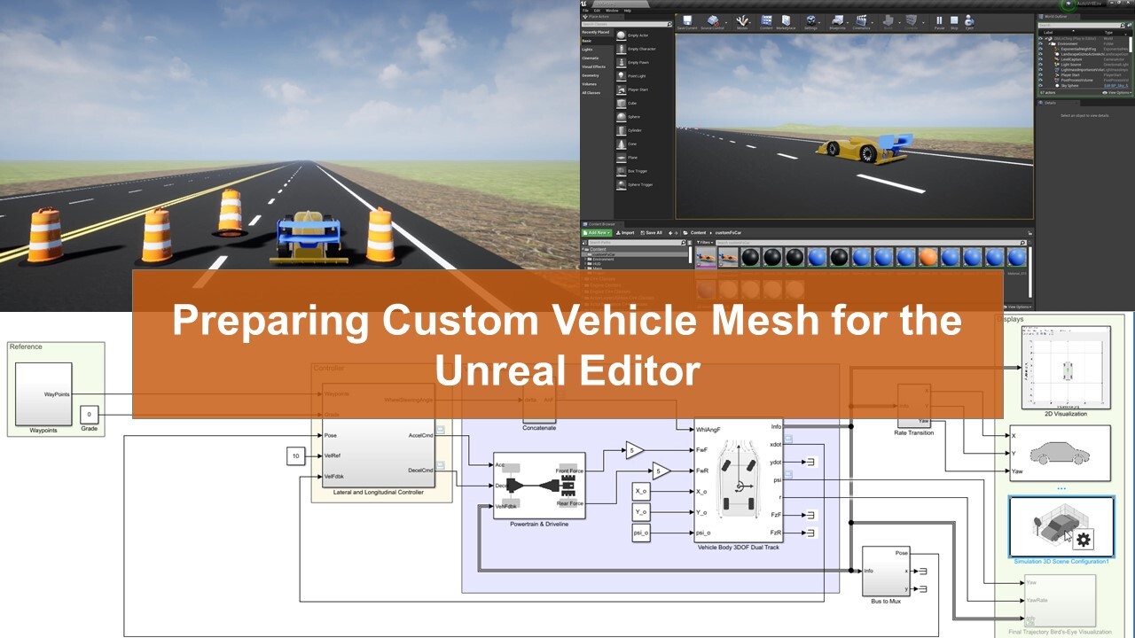
Learn the steps involved in preparing a custom vehicle mesh for the Unreal Editor. Set up the 3D vehicle hierarchy in 3D creation software to create a compatible mesh. Once the required FBX® file is generated, import the file to the Unreal Editor. Finally, discover how to integrate this vehicle mesh with the Simulink model.
Acknowledgment: We would like to thank Amar Birdi from Newcastle University for his contributions to this video creation, including the vehicle mesh.
Published: 18 Feb 2022
Hello and welcome to the MATLAB and Simulink Racing Lodge. In this video, we are going to talk about preparing a custom mesh for the Unreal Editor. First, we'll see how we can import the mesh to a scene already present in the support package to go stimulate with Simulink. And then, we'll also compile a project with a custom scene and a custom vehicle mesh.
Before we jump to the main content of the video there's a prerequisite. The video series using Unreal Engine with Simulink walks you through the process of connecting the Simulink vehicle model to an Unreal Engine scene. It also talks about creating custom scenes. So if you haven't watched it, please have a look, as we have referred to this video series at multiple instances. Assuming you have watched the video series, and have already installed the necessary software and plugins to connect with Simulink model to Unreal Engine. Now let's get started
To create the mesh, we have used Blender which is a 3D computer graphics software tool set. In the first step, we'll define the coordinate system for the vehicle, such as the x-axis points forward, the y-axis points to the left, and the z-axis points up from the ground. Next, to ensure that this measure is compatible with animation components in the vehicle dynamics proximate interface for Unreal Engine 4 project support package, we use the following naming convention for the vehicle parts. For example, for our custom vehicle mesh, we have named the vehicle body and the tires as per the naming convention. Further, we'll set vehicle body as a parent for all the other vehicle objects. Please note that, if you couldn't find certain vehicle objects in the list, just give it a name and assign vehicle body as a parent.
As you can see here that the object of the aero package is not a part of this list, but we have assigned vehicle body as the parent. Optionally, you can also define the material properties. Before exporting the mesh, make sure that the vehicle objects rotations are set to zero and the scale is set to one To do so, select all, and apply rotation landscape. This tip will ensure compatibility with the animation component of the VDBS for Unreal Engine.
Now let's export the mesh. We'll click on File, then export and select the FBX format. This will open the Blender file view page. Now, set the fields as given in the documentation. Then, press export and the FBX file will be generated.
Now that we have the generated FBX file, we'll import it to the Unreal Editor. For this, we'll refer to the double lane change menu and reference application. VIR will let me get to the visualization subsystem. Under the 3D engine block, we will find a simulation 3D scene configuration. In the block, set the scene source to Unreal Editor and mention the Unreal Project in the project section. Then, click on the Open Unreal Editor to launch the editor. This will open the Unreal Editor with a scene.
As we are using the double lane change reference application, we'll change the scene to double lane change by going to the content, then maps, and then double clicking on the double lane change map.
Now that the scene is set, let's import the generated FBX file. First, let's create a folder where we will place the mesh and the supporting files. Next, click Import and select the file you want to import. This will launch the FBX Import Options canvas. Under this, check the skeleton mesh option, and assign the skeleton to the SK_passenger vehicle skeleton asset. If you don't find this skeleton in the dropdown menu, make sure that, in the View Options, you have checked the show Engine Content, and show plug-in contact. Finally start the import, and depending upon the complexity of the mesh, the process will be completed.
Next, to interface this custom vehicle mesh with a Simulink model in the simulation 3D vehicle block, set the vehicle type to custom, and part to the part in the Unreal Editor Project that contains the imported mesh. Please note that the custom vehicle option is also available in the simulation 3D vehicle with Ground Following Block.
Now, let's add the part. To add the part from the Unreal Editor, copy Copy Reference, and delete skeleton mesh and the codes, and paste it to the part. Optionally, you can also change the color of the vehicle.
Now, we are ready to start the code simulation with a custom vehicle mesh. We'll hit the Run button. And once the status changes to initialization, we can click Play and visualize the simulation in Unreal Editor.
So this was a procedure to add a custom vehicle mesh to a scene that is already available in the support package. Similarly, you can also add this custom vehicle mesh to your custom project. For example, this is the custom project where the race track scene has been imported from RoadRunner. The folder here contains imported scene files and the files for the custom vehicle mesh. Now to ensure the actor in the scene communicates with the Simulink model, you'll need to de-parent this project with a level blueprint for which the steps have been demonstrated in the third video of the Using Unreal Engine with similar series.
Once the import is done, we can either run the model in the Unreal Editor, or can package the project file containing the scene and the vehicle into an executable. As we have already run the model in Unreal Editor in the previous example, let's send it in executable mode. For this, we'll need to package the project. To package the project, set the packaging options as mentioned in the documentation. Once that's set, specify the scene from the project that you want to package. In our case, we have added the part of our map.
Next, to the vehicle under Additional Asset Directories to Cook, click the adds element button to add the directory. In our case, we have added a directory of the custom vehicle. Depending upon your use case, you can also add the assets present in the MathWorks simulation directory. Next, rebuild the lighting and package the project.
Once packaging is complete, the folder you have saved the package contains a Windows new editor folder that includes the executable file. To check the executable, we'll use the vehicle part tracking example model available on Get. In the model, we'll set the scene source to executable, specify the project part and the scene name. Then, in the simulation 3D Ground Following, we'll add the part of the custom mesh. Please note that, the part of the scene should be same as that mentioned while packaging, and the part of the custom mesh is obtained using copying reference as explained earlier. Once you are set, you'll be able to run the model without Unreal Editor.
So this was the procedure on how you import a custom mesh and simulated with Simulink models. We hope you will find the video useful to simulate your own custom mesh. Do check out the video and the documentation links provided in the video description. And also, please feel free to reach out to us at racinglounge@mathworks.com in case of any questions, and suggestions. Thank you.
Related Products
Learn More


Seleccione un país/idioma
Seleccione un país/idioma para obtener contenido traducido, si está disponible, y ver eventos y ofertas de productos y servicios locales. Según su ubicación geográfica, recomendamos que seleccione: United States.
También puede seleccionar uno de estos países/idiomas:
América
- América Latina (Español)
- Canada (English)
- United States (English)
Europa
- Belgium (English)
- Denmark (English)
- Deutschland (Deutsch)
- España (Español)
- Finland (English)
- France (Français)
- Ireland (English)
- Italia (Italiano)
- Luxembourg (English)
- Netherlands (English)
- Norway (English)
- Österreich (Deutsch)
- Portugal (English)
- Sweden (English)
- Switzerland
- United Kingdom (English)